1
DIN-Rail Power Switch Meter (PSM-DIN2-ZW Series)
The Power Switch is capable of receiving wireless signals from the coordinator in the Z-Wave network to toggle On/Off of
appliances that are attached to it. The Power Switch also features keeping tracks of energy consumption with built-in
power meter and transmit the data to the Z-Wave network regularly.
The Power Switch is a Z-Wave enabled device and is fully compatible with any Z-Wave enabled network.
Z-Wave is a wireless communication protocol that uses a low-power RF radio. By taking advantage of the Z-Wave mesh
network, commands can be transmitted to their destination via intermediary “listening” Z-Wave products.
The PSM-DIN2-ZW series includes the following models:
PSM-DIN2-ZW
PSM-DIN2-ZW-OTA
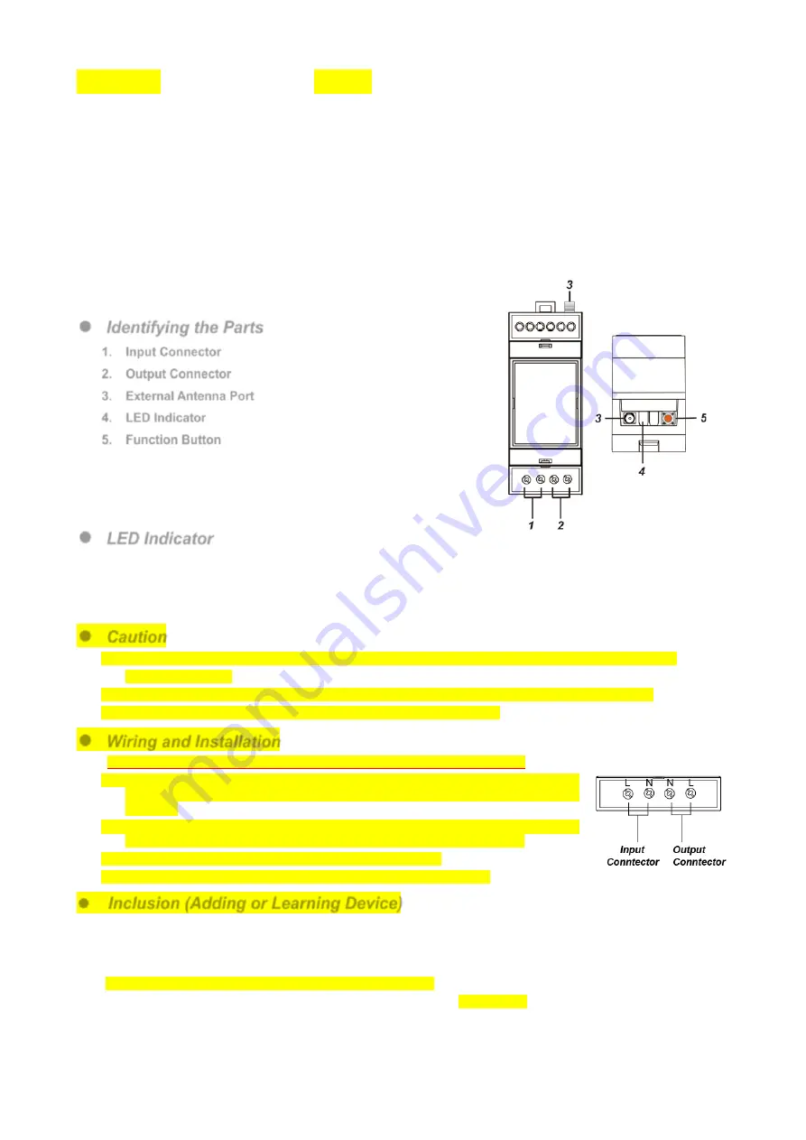
Identifying the Parts
1. Input Connector
2. Output Connector
3. External Antenna Port
4. LED Indicator
5. Function Button
-Press the Function Button 3 times within 1.5 seconds
to send a learn code.
-Press and hold for 10 seconds to factory reset.
LED Indicator
On: power on
Off: power off
Red light flashes twice: 1. The Power Switch has just been powered on,
or
2. The Power Switch has just been factory reset.
Caution
All works on the device, including installation and maintenance, must be performed by a qualified and
licensed electrician.
Before installation or any maintenance work, make sure the power supply has been disconnected.
Do not connect the device to loads exceeding supported load current.
Wiring and Installation
Before installation, make sure the power supply has been disconnected.
Connect L terminal of input connector to the L terminal of Power Supply, please use
fuse for the wire. Connect N terminal of input connector to the N terminal of Power
Supply.
Connect N terminal of output connector to the N terminal of external device, and
connect L terminal of output connector to the L terminal of external device.
Connect the external antenna to the external antenna port.
Mount the device inside the electrical enclosure using a DIN rail.
Inclusion (Adding or Learning Device)
This product can be included and operated in any Z-Wave network with other Z-Wave certified devices from other
manufactures and/or other applications. All non-battery operated nodes within the network will act as repeaters
regardless of vendor to increase reliability of the network.
Power on the device by turning on external power supply.
Put the Z-Wave Gateway or Control Panel into
Inclusion
or
Learning
mode (please refer to the Z-Wave
Gateway or Control Panel manual).
Within 1.5 seconds, press the Function Button 3 times.
Refer to the operation manual of the Z-Wave Gateway or Control panel to complete the adding process.


