67
Step-by-step assembly
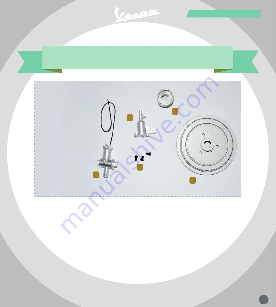
1
Parts in this pack
carburettor and rear brake
1) carburetTor body
2) float chamber
3) rear wheel hub
4) fixing screws
5) rear brake backplate
GS 150
2
stage 17
3
4
5
Page 1: ...67 67 Step by step assembly 1 Parts in this pack carburettor and rear brake 1 carburetTor body 2 float chamber 3 rear wheel hub 4 fixing screws 5 rear brake backplate GS 150 2 stage 17 3 4 5 ...
Page 2: ...arburettor body so the assembly looks like this Align the carburettor with the engine so you can fit the large D shaped lug into hole A and the smaller lug into hole B Take the carburettor body and the float chamber and align them like this ready to fit them together 3 5 1 2 4 6 A B ...
Page 3: ...b axle with the slots in it facing outwards Now take the rear wheel hub You will need to apply some pressure to fit the lugs all the way into their holes To avoid damaging the carburettor press down on the two marked points only and make sure both lugs go in at the same time 10 12 7 8 11 13 9 B ...
Page 4: ...he backplate all the way onto the axle so the lugs go into the hub the three holes indicated line up with the holes in the swingarm and the back of the plate is flush with the face of the swingarm Push the hub all the way in until the outer face of the hub is flush with the swingarm pivot 17 19 14 15 18 16 Note the position of the two slots ...
Page 5: ...rew then add screws in the other two holes Take the three screws provided and use the tip of the screwdriver to fit them into the holes When the third screw is in place go round and tighten all three fully That completes the assembly for this stage 23 25 24 22 21 ...
Page 6: ...72 72 Step by step assembly 1 Parts in this pack ignition coil and rear hub 1 ignition coil plug lead 2 fixing screw 3 register screw 4 rear axle retainer 5 coil bracket GS 150 2 stage 18 3 4 5 ...
Page 7: ...rts together fitting the coil into the back of the bracket and lining up the hole indicated Take the ignition coil and its bracket and align them like this 3 1 2 4 Take the screw provided and use it to fasten the two components together 5 6 7 ...
Page 8: ... the lead into the hole on top of the shroud over the cylinder head The assembly should look like this The two pins on the back of the coil bracket are different sizes Fit them into the matching holes in the engine casing Align the coil and plug lead with the engine 10 8 12 11 9 13 ...
Page 9: ...he gear selector to the furthest notch The assembly should now look like this Take the small register screw provided 16 14 15 17 Compress the spring to release the selector pawl then rotate the selector You may find it helpful to use a screwdriver to move it as shown in Step 19 18 19 20 Step by step assembly ...
Page 10: ...rovides a little extra clearance above the hole you will be working on The register screw should now look like this which completes this stage of the assembly Push it all the way into the hole Holding the register screw with a pair of long nosed pliers line it up with the hole 23 21 25 24 22 26 ...
Page 11: ...77 77 Step by step assembly 1 Parts in this pack rear wheel 1 fixing screws 2 rear wheel inner rim GS 150 2 stage 19 ...
Page 12: ...p assembly Step by step assembly Take the rear wheel rim provided in this pack plus the rear axle retainer provided with Stage 18 Align the parts like this matching up the four mounting holes Fit the parts together 2 1 ...
Page 13: ...ed under the rear bodywork which acts as a mudguard 8 9 Holding the parts together start inserting the fixing screws provided but do not tighten them fully yet 3 4 Continue until you have inserted all four screws then go round and tighten them all fully 5 6 7 Step by step assembly ...
Page 14: ...80 80 Step by step assembly 1 Parts in this pack rear wheel 1 rear wheel outer rim 2 fixing screws GS 150 2 stage 20 ...
Page 15: ...les as shown in Step 2 1 2 This shows the two parts fitting together correctly Note that there is a gap between them and the pins do not go all the way into the recesses 5 6 Fit the parts together making sure that all the locating pins on the outer rim go into the holes in the inner rim 3 4 ...
Page 16: ... fasten the parts together 7 8 When all five screws are in place go round again and tighten them fully to complete the wheel assembly 12 13 9 11 10 Keeping the rims together start inserting the fixing screws provided but do not tighten them fully yet Step by step assembly ...
Page 17: ...83 83 Step by step assembly 1 Parts in this pack rear tyre 1 rear tyre GS 150 stage 21 ...
Page 18: ... on the other side of the wheel Then check that the tyre is evenly seated all round by making sure that the inner circles moulded into the rubber are concentric with the wheel rim If they aren t you can gently bounce the tyre on a flat surface to adjust the position 5 6 As you near the full circle you may find it helps to use a flat tipped screwdriver to ease the beads over the rim Do this gently ...
Page 19: ...85 85 Step by step assembly 1 2 4 3 Parts in this pack headlight assembly 1 headlight glass 2 headlight rim 3 headlight reflector 4 fixing screws GS 150 stage 22 ...
Page 20: ... blue with the locating ribs and mounting posts inside the rim 1 3 2 Press the glass into the frame as shown then take the reflector Match up the notches with the locating ribs in the rim in the same way you did with the lens 4 6 5 Test fit the reflector noting how the three holes in the reflector line up with the mounting posts on the rim They will be used to fix the headlight shell in place 7 8 ...
Page 21: ...e of turns so the end of the screw doesn t protrude through the plastic 12 14 13 Continue until all three screws are retained in the reflector 15 16 It can be tricky to insert the very small fixing screws in one go so we suggest you separate the parts remembering how they fit together while you start to fit the three screws provided ...
Page 22: ... 18 The complete assembly should look like this The peak projecting from the rim will fit at the top of the headlight while the hole in the back is used to fit the light inside the reflector 22 23 Keeping the reflector pressed firmly into the rim so it fits flush all round screw all three screws firmly into the mounting posts 19 21 20 ...
Page 23: ...bly 1 2 4 6 5 3 Parts in this pack right handlebar and brake 1 handlebar fixing screws 2 switch mounting screws 3 cable stop fixing screw 4 switch 5 brake cable retainer 6 right handlebar brake lever and cable GS 150 stage 23 ...
Page 24: ...ing holes circled in red Make sure the switch is the right way up with the black switch lever itself pointing downwards in the direction shown 1 3 2 Take the two smallest silver screws from the pack and use them to fix the switch to the clamp Make sure that the switch is firmly fixed to the clamp 4 7 6 9 5 8 ...
Page 25: ...the brake cable through the two guide just beyond the end of the handlebar indicated in red in Step 13 and press the end of the black outer sheath into the large channel that forms a stop in the further of the two guides Then take the free end of the brake cable down through the oval hole indicated in Step 15 The cable should run like this 13 16 15 18 14 17 Now take the two largest black screws pr...
Page 26: ... cable retainer facing down fit the hole in the round end over the circular lug next to the cable stop Then take the remaining screw Tighten the screw into the hole to fix the cable stop to the handlebar cover securing the end of the brake cable in place and completing this stage of the assembly 22 25 24 27 23 26 Take the brake cable retainer provided ...
Page 27: ... Parts in this pack left handlebar controls GS 150 stage 24 7 1 gear selector spring 2 outer gear selector ratchet 3 inner gear selector ratchet 4 clutch Cable retainer 5 clutch gear selector lever and cable 6 Fixing screws 7 left handlebar ...
Page 28: ...until it stops against the thicker portion then take the inner gear selector ratchet Slip this over the thin end of the handlebar with the toothed side facing outwards Slide the inner gear selector ratchet onto the handlebar until it stops against the spring then take the outer gear selector ratchet which has two lugs on one end 3 5 4 ...
Page 29: ...two sets of teeth mesh together 8 10 9 Slide the lever along the handlebar until it reaches the outer gear selector ratchet Rotate the parts so you can engage the lugs on the ratchet with the notches in the end of the lever clamp as shown in Step 14 Now take the clutch gear selector lever and fit it over the end of the handlebar keeping the cable out of the way 13 14 11 12 ...
Page 30: ...andlebar cover as shown in close up in Step 18 15 17 16 Lead the clutch cable through the guides moulded into the handlebar cover and press the end of the black outer sheath into the stop as indicated in Step 19 Take the two fixing screws provided and use them to fix the end of the handlebar to the handlebar cover 18 19 20 21 ...
Page 31: ...e handlebar securely in place 22 27 23 28 After fixing the handlebar to the handlebar cover lead the cable down through the same hole where you placed the brake cable in the previous stage Both cables should run in a smooth curve 24 26 25 ...
Page 32: ...wn fit the large round hole over the circular lug next to the cable stop 29 31 30 Screw the cable retainer in place with the remaining screw That completes this stage The illustration on the right shows how the assembly appears when the handlebars are in place on the model 32 33 34 35 ...
Page 33: ...w covers 7 are not used until later so be careful not to lose them stage 25 7 1 throttle twistgrip rubber 2 gearchange twistgrip rubber 3 throttle twistgrip 4 gearchange twistgrip 5 throttle twistgip return spring 6 twistgrip end caps 7 screw covers 8 twistgrip retaining screws 8 ...
Page 34: ...he end of the lefthand bar Press the twistgrip into place so it locks into the clutch lever clamp Then take one of the large retaining screws provided and screw it into the end of the handlebar Tighten the screw to secure the twistgrip but do not overtighten it It must be free to rotate on the handlebar Then take the gearchange twistgrip rubber which is the shorter of the two grips supplied 4 7 1 ...
Page 35: ... of the rubber and prevents the rubber from twisting around the grip Push the rubber all the way up to the handlebar clamp Take either of the end caps which are identical and push it into the open end of the rubber Push it all the way in so it snaps into place Slip the remaining twistgrip onto the other handlebar making sure that the large notch at one end is underneath the outer end of the bar as...
Page 36: ...ws the spring correctly located With the slot in the handlebar exposed by the notch in the twistgrip follow the sequence above to fit the spring over the handlebar and hook the inner end in place Note the free end of the spring arrowed in red This will need to fit into the slot arrowed in blue which is done in Step 26 Take the remaining large retaining screw and screw it into the end of the handle...
Page 37: ...ng it back to the start position Fit the second twistgrip rubber which also has a rib to ensure it can only be fitted in one position Slide the rubber all the way onto the twistgrip then take the end cap Press the cap into the end of the twistgrip until it snaps into place That completes the assembly which now has two working twistgrips and levers 30 33 27 32 34 29 31 28 ...