Vertiv
|
NetSure -48V DC Bulk Output Power System Installation and User Instructions (UM582127100)
|
Rev. E
34
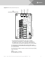
IB2 Controller Interface Board) Connections (if required)
The IB2 (Controller Interface Board) provides connection points for digital inputs, programmable relay outputs,
and temperature probes. The IB2 interface board is mounted inside the main rectifier module mounting shelf.
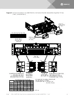
Refer to
Digital Inputs and Programmable Relay Outputs
Digital input and relay output leads are connected to screw-type terminal blocks located on the IB2.
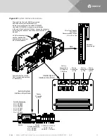
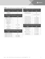
Recommended torque for these connections is 2.2 in-lbs. Refer to
for terminal locations. Refer to
•
Digital Inputs
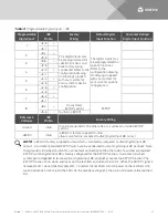
Connect up to eight (8) digital inputs to the IB2. Note that you must supply both paths for the digital input
(either a positive or a negative signal and the opposite polarity return path). Observe proper polarity. Refer to
for terminal locations and
The digital inputs can be programmed to provide an alarm when the signal is applied (HIGH) or removed
(LOW). Refer to the NCU Instructions (UM1M830BNA) for programming information.
Digital Input Ratings: Refer to the following.
a)
Maximum Voltage Rating: 60V DC.
b)
Active High: > 19V DC.
c)
Active Low: < 1V DC.
The digital inputs may be preprogrammed for specific functions. Refer to the configuration drawing (C-
drawing) supplied with your system for your system’s specific configuration.
•
Programmable Relay Outputs
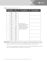
The IB2 provides eight (8) programmable alarm relays with dry Form-C contacts. Connect up to eight (8) relay
outputs to the IB2. Refer to
for terminal locations and
Refer to the NCU Instructions (UM1M830BNA) for programming information.
Relay Ratings: Refer to the following.
a)
Steady State: 0.5 A @ 60V DC; 1.0 A @ 30V DC.
b)
Peak: 3 A @ 30V DC.
The relays may be preprogrammed for specific functions. Refer to the configuration drawing (C-drawing)
supplied with your system for your system’s specific configuration.
Temperature Probes
NOTE!
Each temperature probe consists of two pieces that plug together to make a complete probe.
See SAG582127100 for part numbers and descriptions.
Temperature probes are connected to the IB2 (Controller Interface Board) and/or the system external interface
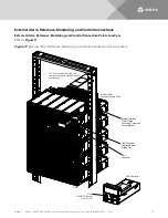
board mounted inside the main rectifier module mounting shelf. See
Up to two (2) temperature probes can be connected to the IB2. Up to two (2) additional temperature probes
can be connected to the system external interface board. Any combination of the four (4) temperature probes

