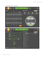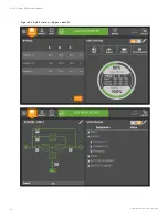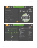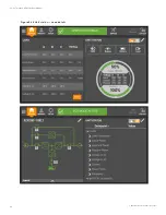
5.7 Alarm List
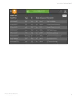
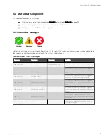
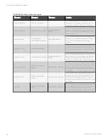
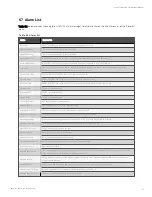
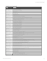
Table 5.4 below provides the complete list of UPS alarm messages for display either on the 'Event' menu or on the 'Records'
menu.
A larm
E xp lanation
Fault Clear
FAULT CLEAR key on the operator control and display panel pressed
Rectifier in Setting
The rectifier starts up and is in synchronization
Inverter in Setting
The inverter starts up and is in synchronization
Inverter Manual On
INVERTER ON key on the operator control and display panel pressed to turn on the inverter
Inverter Manual Off
INVERTER OFF key on the operator control and display panel pressed to turn off the inverter
Turn On Fail
The inverter failed to turn on when the INVERTER ON key is pressed. This may be the result of an invalid operation
(maintenance bypass switch closed) or DC bus or rectifier not ready
Rec. Soft Start Fail
Owing to low DC bus voltage, the rectifier will report this alarm
Silence Active
SILENCE ON/OFF key on the operator control and display panel pressed
Silence Inactive
SILENCE ON/OFF key on the operator control and display panel pressed in alarm silence state
Bypass Mode
The UPS is in bypass mode
Normal Mode
The UPS is in normal mode
Battery Mode
The UPS is in battery mode
Check UPS Output
UPS shutdown with no output power
Output Disabled
EOD event happened. Check the battery voltage
Other Bypass STS Fail
The adjacent bypass STS open circuit fault or short-circuit fault
Input Voltage Abnormal
The mains voltage is outside specifications and results in rectifier shutdown
Input Undervoltage
At least one phase main input voltage is within 132 V to 176 V, thus the load should be derated
Input Freq. Abnormal
The mains frequency is outside specifications and results in rectifier shutdown
Input Phase Reversed
The AC input phase rotation is reversed
Input Backfeed
Battery voltage fed back to rectifier input
Input Neutral Lost
AC rectifier input neutral line not detected
Input Current Abnormal
Battery load sharing imbalance or rectifier input current abnormal
Input Current Limit
Input current over limit
Bypass Unable to Trace
The voltage amplitude or frequency of bypass is out of the range of protection(the range is set in parameter. This alarm
automatically resets once the bypass voltage goes normal
Bypass Abnormal
The amplitude or frequency of the bypass voltage exceeds the limit. This alarm automatically resets once the bypass
voltage returns to normal
Bypass STS Fail
At least one of the STSs at the bypass side is open or shorted. This fault is locked until power-off
Byp. Abnormal Shutdown
Both the bypass and inverter voltages are abnormal, and the output is off
Bypass Phase Reversed
The phase rotation of the bypass voltage is reversed
T able 5.4 A larm list
5 Operator Control and Display Panel
97
Vertiv™ Liebert® APM Plus User Manual
Summary of Contents for APM 0250kMK16FN02000
Page 1: ...Vertiv Liebert APM Plus User Manual 50 250 kVA UPS...
Page 8: ...vi This page intentionally left blank Vertiv Liebert APM Plus User Manual...
Page 30: ...2 Overview 22 This page intentionally left blank Vertiv Liebert APM Plus User Manual...
Page 97: ...5 Operator Control and Display Panel 89 Vertiv Liebert APM Plus User Manual...
Page 188: ...12 Specifications 180 This page intentionally left blank Vertiv Liebert APM Plus User Manual...

