background image

 
String Current Calibration 


590-2106-501A/SL-29421/4200-099 


2.3


Calibration Procedure 

Set up the equipment as shown in figure 1. The positive (+) output of the Calibration source is 
connected to Input 1 (-) and the negative (-) output is connected to Input 2 (+) of the UXIM/UXTM 
through 10K Ohm precision resistors. 


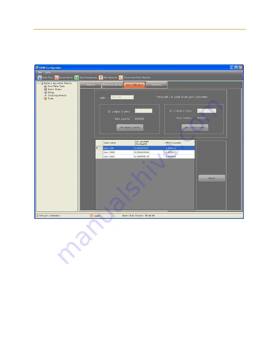
Figure 3 - Tools Gain Calibration 

To calibrate the string current: 

1.


Zero out DMM errors using the method specific for the equipment being used (If using Keithley 
2701, short the inputs then press the REL button). 

2.


Establish a USB connection between the UXIM/UXTM Configurator software and the 
UXIM/UXTM and navigate to the 

Gain Calibration

 tab under the 

Tools

 menu of the 

UXIM/UXTM Configurator software (see Figure 2). 

3.


From the 

Gain

 drop-down box of the 

Gain Calibration

 tab select the gain level to be calibrated 

(Gain 10 for example). 

4.


Adjust the Calibration source to the nominal Input Voltage 1 value for the selected gain level 
(100.100 mV for Gain 10) shown in table 1. 


Summary of Contents for Alber Universal Xplorer Industrial Battery Monitor

Page 1: ...r Industrial and Telecom Monitors UXIM and UXTM Battery Monitor Calibration Guide Vertiv Corporation 1050 Daerborn Drive Columbus OH 43085 Tel 954 377 7101 Fax 954 377 7042 www vertivco com 590 2106 5...

Page 2: ...o be used in performing procedures not specifically described in this document The products covered by this instruction manual are manufactured and or sold by Vertiv This document is the property of V...

Page 3: ...rtiv Customer Service is available Monday to Friday 8 00AM to 4 30PM Eastern Time Telephone 954 377 7101 Fax 954 377 7042 Email alber service vertivco com Website www vertivco com Corporate Office Add...

Page 4: ...00 099 iii Table of Contents 1 Safety Information 1 1 1 General 1 1 2 Document Symbols 1 1 3 Safety Symbols 2 1 4 Product Safety Practices 2 2 String Current Calibration 4 2 1 Equipment Required 4 2 2...

Page 5: ...9 iv List of Figures Figure 1 UXIM Equipment Setup 4 Figure 2 UXTM Equipment Setup 5 Figure 3 Tools Gain Calibration 6 List of Tables Table 1 Calibration Input Voltages 7 Table 2 Calibration Voltages...

Page 6: ...r energize the UXIM UXTM until after the installation is complete Never exceed equipment voltage power ratings or capabilities 1 2 Document Symbols The symbols below appear in this manual or are affix...

Page 7: ...minimize shock hazard the system chassis must be connected to an electrical protective earth ground when required When AC mains are used for the power source the system must be connected to the AC po...

Page 8: ...dify equipment Due to the possibility of introducing additional hazards do not substitute parts or perform any unauthorized modification to the product If necessary contact Vertiv to ensure the safety...

Page 9: ...nt Calibration 2 1 Equipment Required for the UXIM 6 5 digit voltmeter DVM capable of measuring 10uV Keithley 2701 or equivalent Precision 10uV to 500mV DC Voltage Standard Calibration Source EDC MV10...

Page 10: ...5 2 2 Equipment Required for the UXTM 6 5 digit voltmeter DVM capable of measuring 10uV Keithley 2701 or equivalent Precision 10uV to 500mV DC Voltage Standard Calibration Source EDC MV106 or equival...

Page 11: ...rs using the method specific for the equipment being used If using Keithley 2701 short the inputs then press the REL button 2 Establish a USB connection between the UXIM UXTM Configurator software and...

Page 12: ...tual input value indicated by the DVM in the IC 1 input 2 box of the Gain Calibration tab 10 Click Get Input 2 Counts and the Raw Counts value will update 11 Click Get Input 2 Counts a second time aft...

Reviews: