background image


VL-ENCL-5 Reference Manual 


10


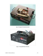
Figure 9. Example PC/104 Board Installation 


Figure 10. Example EBX Board Installation 


Summary of Contents for VL-ENCL-5

Page 1: ...ess mainly focus on the distribution of electronic components Line cards we deal with include Microchip ALPS ROHM Xilinx Pulse ON Everlight and Freescale Main products comprise IC Modules Potentiometer IC Socket Relay Connector Our parts cover such applications as commercial industrial and automotives areas We are looking forward to setting up business relationship with you and hope to provide you...

Page 2: ...Reference Manual DOC REV 4 9 2013 VL ENCL 5 Development Enclosure ...

Page 3: ...no representations or warranties with respect to this product and specifically disclaims any implied warranties of merchantability or fitness for any particular purpose VersaLogic reserves the right to revise this product and associated documentation at any time without obligation to notify anyone of such changes PC 104 and the PC 104 logo are trademarks of the PC 104 Consortium The SUMIT name and...

Page 4: ...ls 1 Technical Specifications 2 Accessories Options 2 Recommended Tools 2 Parts List 3 Metal Parts 3 Hardware 3 Front and Back Panels 4 VL ENCL 5A Front Panel 4 VL ENCL 5B Front Panel 4 VL ENCL 5C Front Panel 5 VL ENCL 5D Front Panel 5 Installation 7 Procedure 7 Enclosure Lid 12 Installation 12 ...

Page 5: ...ive ATX style power supply 5 25 CD ROM drive MODELS There are four models of the VL ENCL 5 which accommodate computers with different interfaces and breakout boards See KnowledgeBase article VT1630 VL ENCL 5 Models for VersaLogic SBCs for information on the appropriate VL ENCL 5 model for your computer Model Front Panel Cutouts Drive Bays VL ENCL5a COM 4 USB 4 LPT floppy PS 2 mouse PS 2 keyboard a...

Page 6: ...t gauge steel Finish Black powder coat Accessories Options The following accessories and options for the VL ENCL 5 are available from VersaLogic VL CDD IDE1 CD RW DVD ROM Internal VL ENCL 3HS Handle set VL ENCL5LID Tilt lid for VL ENCL 5 VL FDD 144 3 5 floppy drive 1 44 MB VL HDD 35 xx 3 5 hard drive VL HDW 101 Metric standoff package PC 104 VL HDW 105 Metric standoff package SUMIT VL HDW 201 PC 1...

Page 7: ...top 4 Rubber feet Hardware kit HDW ENCL5 for the installation of circuit board hardware and devices 7 D Sub jack screw sets for attaching connectors to front and rear panels 20 M3 nuts for use with hex standoffs 12 Black Phillips pan head screws 6 32 x 1 4 for use in securing drives and devices 32 Phillips pan head screws 3mm x 6mm for use in securing drives and standoffs 4 5mm x 10mm M3 hex stand...

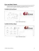
Page 8: ... models have different front panels to accommodate various VersaLogic breakout board and connector configurations Each front panel option is shown below VL ENCL 5A Front Panel Figure 1 VL ENCL 5A Front Panel VL ENCL 5B Front Panel Figure 2 VL ENCL 5B Front Panel ...

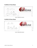
Page 9: ...VL ENCL 5 Reference Manual 5 VL ENCL 5C Front Panel Figure 3 VL ENCL 5C Front Panel VL ENCL 5D Front Panel Figure 4 VL ENCL 5D Front Panel ...

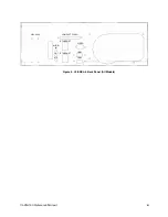
Page 10: ...VL ENCL 5 Reference Manual 6 Figure 5 VL ENCL 5 Back Panel All Models ETHERNET ETHERNET COMPACT FLASH VIDEO USB3 USB4 AUDIO IN OUT MIC CBL 4404 ...

Page 11: ...op bay The drive s power and data connectors should point toward the back panel of the enclosure base Secure 3 5 drives with six 3mm x 6mm screws from the sides or a 2 5 drive with four screws from the top Some drives use 6 32 x 1 4 screws which are also supplied in the hardware kit 4 Attach the breakout board to the base Secure the breakout board to the standoffs installed in step 2 with four M3 ...

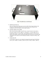
Page 12: ...orrect size standoffs for your computer SUMIT boards must use the standoffs and screws available as part number VL HDW 105 These standoffs are 15 25 mm 0 60 inch and must not be mixed with the 15 0 mm standoffs used for non SUMIT boards Using the standoffs available as VL HDW 101 on SUMIT boards will result in damage to the board Figure 6 Standoff Positions for PC 104 Boards Figure 7 Standoff Posi...

Page 13: ...s and use M3 nuts to secure the board to the enclosure Dual board computers If your computer is a dual board set you must separate the two boards before securing it to the enclosure After separating the boards secure the south board to the enclosure and then re mate the dual board set using care not to bend any pins or misalign the inter board connectors Improper alignment could result in damage t...

Page 14: ...VL ENCL 5 Reference Manual 10 Figure 9 Example PC 104 Board Installation Figure 10 Example EBX Board Installation ...

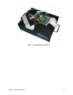
Page 15: ...VL ENCL 5 Reference Manual 11 Figure 11 Example EPIC Board Installation ...

Page 16: ...kit Follow the procedure below to install the lid 1 Remove the two screws from the rear of top enclosure These are two 6 32 x 3 8 screws that will be reused to install the lid 2 Tape the front tabs Cut the 3 foam tape in half and place it on the front tabs 3 Mount the flat pane display Cut the 36 foam tape into appropriate size strips and use it to mount the display 4 Install the shoulder washers ...

Reviews: