


Interfaces and Connectors
EPM-32 Reference Manual
42
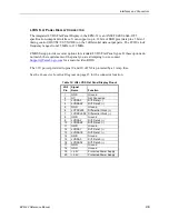
PC/104 Expansion Bus
The EPM-32 will accept up to four PC/104 and four PC/104-
Plus
expansion modules.
A
RRANGING THE
S
TACK
If PC/104-
Plus
modules are used, they go on the stack first (closest to the EPM-32 circuit board).
The first module is called "slot 0," the next module is "slot 1," and the third module is "slot 2."
Make sure to correctly configure the "slot position" jumpers on each PC/104-
Plus
module to
match its physical position in the stack.
PC/104 modules are stacked below the PC/104-
Plus
modules; 16-bit modules first, followed by
8-bit PC/104 modules. Lastly, non-standard modules, which lack feed through connectors, should
be assembled on the bottom of the stack.
I/O
C
ONFIGURATION
PC/104 (ISA Bus) Modules
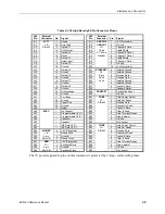
PC/104 I/O modules should be addressed in the 100h – 3FFh, address range. Care must be taken
to avoid the I/O addresses shown in the
table on page 45. These ports are
used by on-board peripherals and video devices.
PC/104-
Plus
(PCI Bus) Modules
The BIOS automatically configures the I/O, memory and interrupt resources of PC/104-
Plus
modules. CMOS Setup may be used to disable modules or select IRQ assignment.