background image

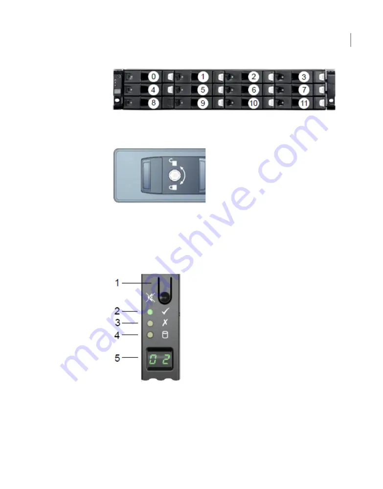
Disk drive carriers in the storage shelf are locked by default. If you need to replace
a locked disk drive use a screwdriver with a T10 bit to unlock each carrier.

The lock is located on the left side of each carrier.

Storage shelf control panel

The left, front, of the storage shelf contains the system control panel.

Components of the control panel include the following.

1.

The Input switch enables you to set the Unit Identification display.

2.

The Power On/Standby LED is amber when only standby power is available.
The LED is green when system power is available.

11

Hardware overview

Storage shelf control panel

Summary of Contents for NetBackup 5240

Page 1: ...NetBackup Appliance Hardware Installation Guide Release 2 7 3 NetBackup 5240 Document Revision 1 ...

Page 2: ...itten authorization of Veritas Technologies LLC and its licensors if any THE DOCUMENTATION IS PROVIDED AS IS AND ALL EXPRESS OR IMPLIED CONDITIONS REPRESENTATIONS AND WARRANTIES INCLUDING ANY IMPLIED WARRANTY OF MERCHANTABILITY FITNESS FOR A PARTICULAR PURPOSE OR NON INFRINGEMENT ARE DISCLAIMED EXCEPT TO THE EXTENT THAT SUCH DISCLAIMERS ARE HELD TO BE LEGALLY INVALID VERITAS TECHNOLOGIES LLC SHALL...

Page 3: ...page 2 The latest documentation is available on the Veritas website https sort veritas com documents Documentation feedback Your feedback is important to us Suggest improvements or report errors or omissions to the documentation Include the document title document version chapter title and section title of the text on which you are reporting Send feedback to APPL docs veritas com You can also see ...

Page 4: ......

Page 5: ...ons 17 Best practices for rack installation 18 Heat dissipation 19 Determining SAS 3 cable length 19 Prerequisites for IPMI configuration 20 Chapter 3 Installation procedures 23 Installing the storage shelf rack rails 23 Installing the storage shelf into a rack 25 Installing the appliance rack rails 26 Installing the appliance into a rack 31 Understanding appliance and storage shelf connections 34...

Page 6: ...an appliance 95 Connecting two storage shelves to an appliance 98 Connecting three storage shelves to an appliance 101 Connecting four storage shelves to an appliance 107 Connecting the network cables 113 Connecting the power cords 114 Turning on the hardware and verifying operation 115 Appendix B Adding storage shelves to an operating 4TB appliance that has at least one storage shelf attached 125...

Page 7: ...figuration Product documentation About the appliance and the storage shelves The NetBackup 5240 appliance and storage shelves provide storage capacity in several configurations You can use the appliance by itself to achieve 4TB 14TB or 27TB of useable capacity You can add storage shelves to a 4TB appliance to further increase the storage capacity Refer to the NetBackup 5240 Product Description at ...

Page 8: ...slots Disk drive role Appliance storage capacity Disk drive size RAID configuration Slot Boot swap N A 1TB RAID 1 0 1 Log files N A 1TB RAID 1 2 3 User storage data 4TB 14TB 27TB 1TB 3TB 6TB RAID 6 4 10 Hot spare N A 1TB 3TB 6TB RAID 6 11 Appliance control panel The front panel of the NetBackup 5240 Appliance includes a small panel that is attached to the right side of the device Hardware overview...

Page 9: ...k activity determines the rate of blinking NIC 1 Activity LED 3 The System Cold Reset button restarts and re initializes the appliance System Cold Reset Button recessed a tool is required for use on non storage models 4 The System Status LED uses the colors green and amber to display the health of the appliance System Status LED 5 The Power Sleep button turns off the appliance or turns on the appl...

Page 10: ...rd that is required with one or more storage shelves 7 Riser Assembly 3 Slot 7 reserved for the SAS RAID HBA card that provides RAID1 support for the appliance storage disk drives 8 Two slots that are not used at this time Note The embedded Ethernet ports are copper PCIe Ethernet ports are fibre You cannot bond the copper ports and the fibre ports to each other Refer to the Veritas NetBackup 5240 ...

Page 11: ...each carrier Storage shelf control panel The left front of the storage shelf contains the system control panel Components of the control panel include the following 1 The Input switch enables you to set the Unit Identification display 2 The Power On Standby LED is amber when only standby power is available The LED is green when system power is available 11 Hardware overview Storage shelf control p...

Page 12: ...s and two I O Module canisters The PCMs located on the left and the right sides of the storage shelf contain fans The I O module canisters are located in the center of the rear panel one above the other Each I O module contains three SAS 3 ports A B and C The SAS ports connect the I O modules to the appliance and to other storage shelves Note that the port labels are reversed on the bottom caniste...

Page 13: ...anagement Interface or IPMI provides management and monitoring capabilities independently of the host system s CPU firmware and operating system You can configure the IPMI sub system for your appliances You can use the remote management port located on the rear panel of the appliance to connect to the IPMI sub system The following figure shows the remote management port or the IPMI port on the rea...

Page 14: ...appliance from a remote location Provides out of band management and help manage situations where local physical access to the appliance is not possible or preferred like branch offices and remote data center In case the appliance is not accessible using regular network interfaces you can access the NetBackup Appliance Shell Menu remotely using IPMI Reimage the appliance from the IPMI interface by...

Page 15: ...ble length Prerequisites for IPMI configuration Customer provided environment and supplies For best ventilation the rack cabinet Should be at least 100 cm 4 feet from walls Should have at least 100 cm 4 feet from other cabinets on the front and back of the appliance and the storage shelves Data centers with two foot spaces in the front and in the back of the appliances are acceptable with proper c...

Page 16: ... boxes and contents The disk drives are installed into the appliance and the storage shelf at the factory The following items ship within the storage shelf box Open Me First box containing Installation flip cards Deployment plan that provides basic information and links to detailed information Rack mounting template Installation poster Cabling poster Rack rails Two SAS 3 cables Two power cords Bez...

Page 17: ...ocations The appliance and the storage shelves are both two rack units 2RU high To help you identify RU spacing many rack manufacturers typically use a system of lines and sequential numbers starting at the bottom of the rack The front and the rear of the rack are marked the same to ensure that the rails are installed straight and level One RU has three holes The holes for one RU are typically mar...

Page 18: ...hem easily when mounting the hardware Best practices for rack installation Prepare for the hardware installation by following these recommendations The storage shelves are heavier than the appliance and should be installed as close to the bottom of the rack as possible Determine device order and cabling limits Be aware of the depth of the guide rails and the devices Ensure that the distance betwee...

Page 19: ... A minimum of 6 inches 15 2 cm of space must be between the rear of an appliance and the cabinet rear or other air block A minimum of 1 inch 2 5 cm of space must be between the front of a storage shelf and the cabinet door or other air block A minimum of 2 inches 5 0 cm of space must be between the rear of a storage shelf and the cabinet rear or other air block Veritas strongly recommends that cus...

Page 20: ... auto negotiate its link speed of up to 1 Gbps Note If the IPMI is connected to a managed switch port it is recommended that you configure the switch port to auto negotiation If a firewall exists between the appliance and the remote devices that manage an appliance like a laptop computer open the following ports SSH 22 HTTP 80 SNMP 162 HTTPS 443 KVM 623 RMM ISO CD 5120 RMM floppy 5123 CD 5124 SSL ...

Page 21: ... The remote management port must be configured as a DHCP or static address 21 Preinstallation requirements Prerequisites for IPMI configuration ...

Page 22: ...Preinstallation requirements Prerequisites for IPMI configuration 22 ...

Page 23: ...r cords Turning on the hardware and verifying operation Configuring the IPMI from the NetBackup Appliance Shell Menu Accessing and using the Veritas Remote Management interface Installing the storage shelf rack rails Best practices recommend that the storage shelves are installed lower in the rack than the appliance There must be a minimum depth of 76 cm 30 in between the front of the rack and the...

Page 24: ...nd the right hand rails Red arrows show the pins that fit into the rack 2 Use the rack templates to align the rails with the rack holes Be sure to use the same holes on each side of the rack Fold the template at the dotted yellow lines to get accurate rail and rack matching Installation procedures Installing the storage shelf rack rails 24 ...

Page 25: ...he right rail Installing the storage shelf into a rack The storage shelf should be installed from the front of the rack To install a storage shelf 1 Use two people to lift the storage shelf 2 Slide the rear of the shelf into the front of the rails Be sure that the shelf is straight and even inside the rack Do not force the shelf to fit 3 Carefully push the shelf towards the rear of the rails 25 In...

Page 26: ...g the appliance rack rails The NetBackup 5240 Appliance requires two RUs of space Veritas recommends that you install the appliance in the space that is directly above the storage shelves Veritas recommends that two people install the rails one person at the back of the rack and one at the front Veritas also recommends that two people lift and place the appliance into the mounted rails Installatio...

Page 27: ...stalled The small metal extensions that are outlined in the illustration must point down towards the floor of the rack Note The information in this document supersedes any of the information in the printed installation materials 2 Use the rack templates to align the rails with the rack holes Fold the template along the yellow dotted lines to create an exact physical match to the rack Be sure to us...

Page 28: ...es and the bottom holes of the top RU Move the rail front and back to fit into the rack Slide the rail forward until the pins click into the rack holes 4 Secure the rear of the rail Push the blue lock toward the rack wall and toward the back of the rail The lock must be behind the rack post Ensure that the lock clicks into place Installation procedures Installing the appliance rack rails 28 ...

Page 29: ...ar of the rack 6 Repeat steps 3 through 5 for the other rail 7 Identify the three different rails in each rail assembly Components in this illustration are as follows 1 Outer rail 2 Intermediate rail 3 Inner rail 29 Installation procedures Installing the appliance rack rails ...

Page 30: ...8 Pull the white tab forward to release the inner rail from the outer and the intermediate rail Installation procedures Installing the appliance rack rails 30 ...

Page 31: ...the appliance rails have been installed you can install the appliance into the rack To install the appliance into the rack 1 Verify that the rails are securely attached Verify that the outer rail is securely attached to the rack Pull the intermediate rail forward Ensure that the ball bearing retainer is locked forward Verify that the inner rail is securely attached to the appliance 2 Place the app...

Page 32: ...e rail forward Ensure that the ball bearing retainer on the intermediate rail is locked forward Note You do not need to extend the rails as far as they can possibly extend You only need sufficient space to place the appliance into the rails Installation procedures Installing the appliance into a rack 32 ...

Page 33: ... the intermediate rail in the rack Slide the appliance forward into the rack The rail has a lock mechanism that prevents the appliance from being fully pushed into the rack 33 Installation procedures Installing the appliance into a rack ...

Page 34: ...re the captive screws on the appliance ears Understanding appliance and storage shelf connections You cannot use SAS 2 cables with the storage shelf You must use the SAS 3 cables that are provided with each storage shelf Installation procedures Understanding appliance and storage shelf connections 34 ...

Page 35: ... PCIe ports on the rear panel of the appliance are in Slot 1 of Riser 2 There are two I O module canisters in the middle of the rear panel of the storage shelf Each I O module includes three SAS 3 ports The SAS 3 ports on the top I O module canister are labeled A B and C from left to right 35 Installation procedures Understanding appliance and storage shelf connections ...

Page 36: ...3 cable connector is very important Storage shelf orientation is as follows The blue clip in the connector in the top I O module of each shelf must point down The blue clip in the connector in the bottom I O module of each shelf must point up In the appliance the blue clips must point down Installation procedures Understanding appliance and storage shelf connections 36 ...

Page 37: ... See Connecting a 4TB appliance to one storage shelf on page 37 See Connecting a 4TB appliance to more than one storage shelf on page 39 Connecting a 4TB appliance to one storage shelf The steps in this section assume that the 4TB appliance and the storage shelf are shipped together and installed at the same time 37 Installation procedures Connecting a 4TB appliance to one storage shelf ...

Page 38: ... RAID PCIe card on the appliance Note Cables in the following diagrams are shown in different colors for demonstration purposes only The actual cables are black 2 Connect the other end of the cable to port A in the top canister of the storage shelf Installation procedures Connecting a 4TB appliance to one storage shelf 38 ...

Page 39: ...ection assume that the 4TB appliance and the storage shelves are shipped together and installed at the same time You can add one or more storage shelves to an operational 4TB appliance Refer to one of the following Appendices for instructions Appendix A Adding one or more storage shelves to an operating 4TB appliance that does not have any storage shelves Overview Appendix B Adding storage shelves...

Page 40: ...ppliance to storage shelves 1 Connect the appliance external RAID controller left port to port A on the top canister of the storage shelf Installation procedures Connecting a 4TB appliance to more than one storage shelf 40 ...

Page 41: ...shelf top canister port B to next storage shelf top canister port A Follow the diagrams until all storage shelf top canisters are connected 41 Installation procedures Connecting a 4TB appliance to more than one storage shelf ...

Page 42: ...Installation procedures Connecting a 4TB appliance to more than one storage shelf 42 ...

Page 43: ...43 Installation procedures Connecting a 4TB appliance to more than one storage shelf ...

Page 44: ...3 Connect the appliance external RAID card right port to the last storage shelf bottom canister port A Installation procedures Connecting a 4TB appliance to more than one storage shelf 44 ...

Page 45: ...ttom canister port B to the next storage shelf bottom canister port A 5 Connect another cable to the shelf that is second from the bottom Use port B on the lower canister of that shelf 45 Installation procedures Connecting a 4TB appliance to more than one storage shelf ...

Page 46: ...nect the other end of the cable to the shelf that is third from the bottom Use port A on the lower canister of that shelf Installation procedures Connecting a 4TB appliance to more than one storage shelf 46 ...

Page 47: ...r panel of the device The remote management port is for use by Veritas Technical Support staff or by approved field service technicians The following picture shows the layout of the network ports It includes the four 1 Gb Ethernet ports on the right and the two 10 Gb Ethernet ports on the left The remote management IPMI port is located to the left of the 1 Gb Ethernet ports 47 Installation procedu...

Page 48: ... See Connecting the power cords on page 48 Connecting the power cords Each appliance and each storage shelf contain two AC power supplies To ensure power redundancy connect the power supplies on each component to separate AC power sources Caution Do not turn on the power to any components while connecting the power cords The components must be turned on in a specific sequence to ensure correct com...

Page 49: ...operation on page 49 Turning on the hardware and verifying operation The appliance and the storage shelves must be turned on in a specified order If the hardware is not turned on correctly the appliance RAID controller may not recognize some storage units 49 Installation procedures Turning on the hardware and verifying operation ...

Page 50: ...Start with the storage shelf that is farthest in distance from the appliance 2 Flip on the power switches on each power supply on the rear of the storage shelf Installation procedures Turning on the hardware and verifying operation 50 ...

Page 51: ...power module is green The LED icons are explained in the following table Description LED Green power module ok Amber AC power fault Amber Fan fault Amber DC fault 51 Installation procedures Turning on the hardware and verifying operation ...

Page 52: ... mark indicates an I O module canister fault when the LED is amber The LED in the ID area is blue when each module is identified The LED in the green area with a white checkmark is green when functions are normal Installation procedures Turning on the hardware and verifying operation 52 ...

Page 53: ...EDs Note that the combination of both LEDs provides the status Fault amber LED Activity green LED Status Off Off No cable present Off On Cable present no activity Off Blinking if one or more disk drives are active Cable present all links active On Off Critical fault Blinking at a rate of one second on and one second off Blinking if one or more disk drives are active Non critical fault 6 Move to th...

Page 54: ...ndby LED is green If the Power LED or the other two LEDs are amber escalate the issue The default ID readout is 00 You are not required to change this number Installation procedures Turning on the hardware and verifying operation 54 ...

Page 55: ...tional Blinks at a rate of one second on and one second off On Device identity On Off Drive slot fault On On Drive fault Power control circuit fault Blinks at a rate of one second on and one second off On Possible drive fault 9 Repeat these steps for each storage shelf Let each shelf initialize before you turn on the next shelf Initialization should take 2 minutes to 3 minutes 10 When all of the s...

Page 56: ...een The following table provides details of the disk drive LEDs Description States LED number name and location No fault Disk fault A RAID rebuild is in progress Off Solid amber Blinking amber 1 Status LED top Power is on and the disk has spun down Power is on but there is no disk activity Power is on and the disk is spinning up Commands are processing Off Solid green Blinking green Blinks green o...

Page 57: ...ble connectivity between your network computer and the remote management port Subnet mask Enable connectivity between your network computer and the remote management port Gateway IP address The defaults for the remote management port are IP Address 192 168 0 10 Subnet Mask 255 255 255 0 Also review the following section on the IPMI prerequisites See Prerequisites for IPMI configuration on page 20 ...

Page 58: ...nfigure the remote management port IPMI Network Configure IPAddress Netmask GatewayIPAddress where IP address is the new IP address of the remote management port The Subnet mask and Gateway enable connectivity between your network computer and the remote management port The remote management port must be configured as a DHCP or static address At any point in time you can run the following command ...

Page 59: ...in a web browser 10 The appliance is ready for initial configuration See the NetBackup Appliance Initial Configuration Guide for the appropriate platform for information about initial configuration requirements and procedures Note Once the initial configuration has been completed you can connect NIC1 eth0 to an administrative network that does not provide any backup data transfer 59 Installation p...

Page 60: ...e 2 Open the Local Area Connection Properties dialog box by right clicking on the local area connection and selecting Properties On the General tab select Internet Protocol TCP IP and then click Properties Note This step may differ for specific OS versions Check your OS documentation for reference Installation procedures Configuring the IPMI from the NetBackup Appliance Shell Menu 60 ...

Page 61: ...t the connection by using the following method Open a secure shell SSH connection to 192 168 229 233 using an SSH client Once the NetBackup Appliance Shell Menu opens with a user name and password prompt you have successfully connected to the appliance for initial configuration 6 When the NetBackup Appliance Shell Menu appears log on using the user name and password for the appliance By default th...

Page 62: ...opriate platform for information about initial configuration requirements and procedures Note Once the initial configuration has been completed you can connect NIC1 eth0 to an administrative network that does not provide any backup data transfer Accessing and using the Veritas Remote Management interface The IPMI web interface is known as Veritas Remote Manager You can use Veritas Remote Manager t...

Page 63: ... LAN channel s To access and use the IPMI web interface from a remote computer 1 Log on to a remote computer in the network and open a supported Windows browser 2 Enter the remote management port IP address that is assigned to the remote management port The following page appears 3 Enter your login information The default user name is sysadmin The default password is P ssw0rd where 0 is the number...

Page 64: ...he Console Redirection tab to launch the appliance NetBackup Appliance Shell Menu The following figure shows the interface for a 5220 5230 or a 5330 appliance The following figure shows the interface for a 5240 appliance Installation procedures Accessing and using the Veritas Remote Management interface 64 ...

Page 65: ...MI port The warning states that you do not have proper permissions and prevents appliance access from the IPMI port For information about how to resolve this issue refer to the following document http www veritas com support TECH212531 6 You can now access and log on to the NetBackup Appliance Shell Menu Enter the user name and password for the appliance By default the user name admin has the pass...

Page 66: ...Installation procedures Accessing and using the Veritas Remote Management interface 66 ...

Page 67: ...liance Removing the appliance cover Installing the External Storage Kit components Reinstalling the appliance into the rack Storage shelf rack requirements Determining rack locations Installing the storage shelf rails Installing the storage shelf or shelves into a rack Understanding appliance and storage shelf connections Connecting one storage shelf to an appliance A Appendix ...

Page 68: ...elves The NetBackup 5240 External Storage Kit contains the following required hardware components One external RAID controller PCIe card Eight 8Gb Dual in line memory modules DIMMs One Maintenance Free super cap Backup Module MFBU Kit The procedures in this appendix explain the following tasks Installing the External Storage Kit components into the appliance Installing one or more storage shelves ...

Page 69: ...To perform a soft shutdown of the appliance 1 Log on to the NetBackup Appliance Shell Menu 2 Enter Support Shutdown 3 Verify that the appliance is completely turned off All LEDs are off Fans are not running 4 Remove the power cords that connect the appliance to the rack Power Distribution Units PDUs The following procedure explains the process of removing the appliance from the rack To remove the ...

Page 70: ...lace your free hands under the back of the chassis for support 10 Pull the appliance straight out of the rack 11 Lift the appliance and place it on a secure surface Removing the appliance cover The appliance cover must be removed to install the components of the External Storage Kit Caution Veritas service personnel must perform all tasks that involve the inside of the appliance chassis Adding one...

Page 71: ...g the External Storage Kit components This section explains the process of installing the three components of the External Storage Kit into the appliance Note that there are three separate procedures one for each type of component Install the hardware in the order that the procedures are presented Caution Veritas service personnel must perform all tasks that involve the inside of the appliance cha...

Page 72: ... the equipment you must observe appropriate electrostatic safety precautions to prevent personnel injuries or device damage 2 Locate the air duct The following table defines the air duct and related components Description Number Air duct arms qty 2 1 Air duct qty 1 2 Fans qty 6 3 Adding one or more storage shelves to an operating 4TB appliance that does not have any storage shelves Installing the ...

Page 73: ...semblies 4 Standing at the front of the appliance press both arms slightly to the right Do not break the arms or the tabs The clear tabs disengage from under the blue frames 73 Adding one or more storage shelves to an operating 4TB appliance that does not have any storage shelves Installing the External Storage Kit components ...

Page 74: ...metal plate on the air duct 6 Disconnect the MFBU battery cable from the cable on the SAS HBA card in Riser Assembly 3 Adding one or more storage shelves to an operating 4TB appliance that does not have any storage shelves Installing the External Storage Kit components 74 ...

Page 75: ... side and in the middle of the two CPU heat sinks Some DIMM sockets are empty Each DIMM socket has an identifier on the main board that consists of a two digit alphanumeric character that indicates the channel and socket for each DIMM Socket identifiers have the format A1 A2 B1 B2 C1 C2 etc The letter defines the channel and the number indicates the socket 75 Adding one or more storage shelves to ...

Page 76: ...uire the addition of a DIMM DIMMs C2 D2 B2 A2 G2 H2 F2 and E2 are indicated with red arrows in the illustration 13 Start with socket C2 on the left side 14 Open the retaining clips at each end of the socket 15 Caution Always hold the edges of the DIMM Do not touch the front or the back of the DIMMs Lift one DIMM from its ESD compliant wrapper Adding one or more storage shelves to an operating 4TB ...

Page 77: ... place 21 Repeat these steps for the remaining seven DIMMs The remaining slots that require additional DIMMs are D2 B2 A2 G2 H2 F2 and E2 22 Do not replace the air duct or the cover at this time 23 Refer to the next procedure to install the external RAID PCIe card MFBU To install an external RAID PCIe card MFBU 1 Put on an ESD compliant wrist strap or take other ESD protective measures 2 Obtain th...

Page 78: ...ll the MFBU onto the metal bracket on the air duct Make sure that the MFBU snaps in evenly 8 Be sure that the cable on the MFBU points toward the rear of the appliance and to the PCIe riser assemblies Adding one or more storage shelves to an operating 4TB appliance that does not have any storage shelves Installing the External Storage Kit components 78 ...

Page 79: ...nd 3 2 Disconnect the cable that is connected to the SAS HBA card in slot 7 Label the port where the cable is connected 79 Adding one or more storage shelves to an operating 4TB appliance that does not have any storage shelves Installing the External Storage Kit components ...

Page 80: ...ot to damage any PCIe cards or HBA cards that are already installed in riser 2 and riser 3 6 Locate three components of riser 2 The screw that secures the External RAID PCIe card in riser 2 The socket in slot 1 on riser 2 into which the External RAID PCIe card is inserted The gold pins at the bottom of the riser which fit into the socket on the main board Adding one or more storage shelves to an o...

Page 81: ...ot 1 of riser 2 8 Align the connector on the PCIe card with the bottom socket Slot 1 on riser 2 The edge connector is designed to install one way only 81 Adding one or more storage shelves to an operating 4TB appliance that does not have any storage shelves Installing the External Storage Kit components ...

Page 82: ...card into the socket 10 Screw the PCIe card into the PCIe riser assembly frame Adding one or more storage shelves to an operating 4TB appliance that does not have any storage shelves Installing the External Storage Kit components 82 ...

Page 83: ...nal RAID PCIe card 13 Reinstall the PCIe riser 2 and 3 unit Align the gold pin connectors of the riser unit with the socket in the main board Press the riser down straight and firmly into the socket 83 Adding one or more storage shelves to an operating 4TB appliance that does not have any storage shelves Installing the External Storage Kit components ...

Page 84: ...the cover with the edge along the top of the chassis Place the cover on the chassis so that there is about 1 5 inches of overhang Slide the cover forward until the edge slides under the lip of the enclosure Secure the cover by doing one of the following Do the following Tighten the two thumb screws circled on the rear panel If the cover looks like this Adding one or more storage shelves to an oper...

Page 85: ... the appliance into the rack To reinstall the appliance 1 Pull the rack rails forward until they are extended far enough that you can place the appliance into the rails 2 Carefully align the appliance rails with the rack rails Slide the blue tab on the outer rail and push the appliance into the rack until it locks 85 Adding one or more storage shelves to an operating 4TB appliance that does not ha...

Page 86: ... necessary personnel and equipment that customers must supply at the installation site At least one person or a mechanical lift to move the appliance and the storage shelves Ethernet and Fibre Channel FC cables to connect the appliance to your corporate network A USB keyboard and a monitor to connect to the appliance A 19 inch rack with dual Power Distribution Units PDUs with 120VAC or 220VAC powe...

Page 87: ...To determine rack locations for the storage shelves 1 A storage shelf is 2RU high Multiply the number 2 by the number of shelves that you plan to install 2 Use the rack templates that are provided with the hardware to determine RU locations The templates show the front and rear of a storage shelf in a rack 87 Adding one or more storage shelves to an operating 4TB appliance that does not have any s...

Page 88: ...NetBackup 5240 Appliance and the NetBackup 5240 Storage Shelf are both 2RU high 2 SAS cables are 1 meter 3 28 feet or 3 meter 9 84 feet long The 1 meter cable is long enough to connect an appliance to the fourth storage shelf assuming that the recommended configuration is used Verify that your cables are long enough to connect all of the devices 3 Order the 3m cable if the 1m cable is not long eno...

Page 89: ...s into a rack 1 Identify the front and the rear of each rail The following illustration shows the front of the left hand and the right hand rails Red arrows show the pins that fit into the rack 2 Use the rack templates to align the rails with the rack holes 3 Fold the templates along the dotted yellow lines to match the holes in the rack Be sure to use the same holes on each side of the rack 89 Ad...

Page 90: ...ves into a rack The storage shelf should be installed from the front of the rack To install a storage shelf 1 Use two people to lift the storage shelf 2 Slide the rear of the shelf into the front of the rails Be sure that the shelf is straight and even inside the rack Do not force the shelf to fit 3 Carefully push the shelf towards the rear of the rails Adding one or more storage shelves to an ope...

Page 91: ...ections You cannot use SAS 2 cables with the storage shelf You must use the SAS 3 cables that are provided with the product The blue clip on each SAS 3 connector must be oriented correctly as follows Both SAS 3 connectors in the ports in the External RAID PCIe card of the appliance must be installed with the blue clip pointing down 91 Adding one or more storage shelves to an operating 4TB applianc...

Page 92: ... I O module canister of each storage shelf must have the blue clip pointing up The SAS connector blue clip should face towards the SAS label on each port in the storage shelf Adding one or more storage shelves to an operating 4TB appliance that does not have any storage shelves Understanding appliance and storage shelf connections 92 ...

Page 93: ...93 Adding one or more storage shelves to an operating 4TB appliance that does not have any storage shelves Understanding appliance and storage shelf connections ...

Page 94: ... in Riser Assembly 2 Slot 1 The SAS ports on the top I O module canister are labeled A B and C from left to right The SAS ports on the bottom I O module canister are labeled C B and A from left to right Adding one or more storage shelves to an operating 4TB appliance that does not have any storage shelves Understanding appliance and storage shelf connections 94 ...

Page 95: ...pliance on page 107 Connecting one storage shelf to an appliance Note The cables in the following diagrams are shown in different colors for demonstration purposes only The actual cables are black To connect one storage shelf to the appliance 1 Connect a SAS 3 cable to the left RAID port in the appliance 2 Be sure that the blue clip on the cable connector in the appliance port points down 95 Addin...

Page 96: ...ule of the storage shelf 4 Be sure that the blue clip on the end of the connector in the storage shelf points down Adding one or more storage shelves to an operating 4TB appliance that does not have any storage shelves Connecting one storage shelf to an appliance 96 ...

Page 97: ...f port A points up 7 Be sure that the blue clip on the connector in the appliance points down Next connect network and power cables Turn on the storage shelves and the appliance per the required sequence Verify that all units are functioning correctly 97 Adding one or more storage shelves to an operating 4TB appliance that does not have any storage shelves Connecting one storage shelf to an applia...

Page 98: ...AS 3 cable to the left RAID port in the appliance 2 Be sure that the blue clip on the connector in the appliance port points down 3 Connect the other end of this cable to port A in the top I O module of the storage shelf 4 Be sure that the blue clip on the connector in port A points down Adding one or more storage shelves to an operating 4TB appliance that does not have any storage shelves Connect...

Page 99: ...r end of this cable to port A in the top I O module in the second storage shelf 6 Be sure that the blue clip on the connectors in these ports point down 99 Adding one or more storage shelves to an operating 4TB appliance that does not have any storage shelves Connecting two storage shelves to an appliance ...

Page 100: ...s port points up 9 In the bottom I O module of the first shelf connect the other end of the cable to port A 10 Be sure that the blue clip on the connector in this port points up Adding one or more storage shelves to an operating 4TB appliance that does not have any storage shelves Connecting two storage shelves to an appliance 100 ...

Page 101: ... the appliance per the required sequence Verify that all units are functioning correctly Connecting three storage shelves to an appliance Note The cables in the following diagrams are shown in different colors for demonstration purposes only The actual cables are black 101 Adding one or more storage shelves to an operating 4TB appliance that does not have any storage shelves Connecting three stora...

Page 102: ...ctor in the appliance port points down 3 Connect the other end of this cable to port A in the top I O module of the storage shelf 4 Be sure that the blue clip on the connector in port A points down Adding one or more storage shelves to an operating 4TB appliance that does not have any storage shelves Connecting three storage shelves to an appliance 102 ...

Page 103: ... end of the cable to port A in the top I O module in the second storage shelf 6 Be sure that the blue clip on the connectors in these ports point down 103 Adding one or more storage shelves to an operating 4TB appliance that does not have any storage shelves Connecting three storage shelves to an appliance ...

Page 104: ...nd of the cable to port A in the top I O module in the third shelf 8 Be sure that the blue clip on the connectors in these ports point down Adding one or more storage shelves to an operating 4TB appliance that does not have any storage shelves Connecting three storage shelves to an appliance 104 ...

Page 105: ...t in the appliance External RAID PCIe card 10 Be sure that the blue clip on the connector in port A points up The blue clip in the appliance port connector should point down 105 Adding one or more storage shelves to an operating 4TB appliance that does not have any storage shelves Connecting three storage shelves to an appliance ...

Page 106: ...ottom I O module in the third shelf to port A in the bottom I O module in the second shelf Adding one or more storage shelves to an operating 4TB appliance that does not have any storage shelves Connecting three storage shelves to an appliance 106 ...

Page 107: ...power cables Turn on the storage shelves and the appliance per the required sequence Verify that all units are functioning correctly Connecting four storage shelves to an appliance Note The cables in the following diagrams are shown in different colors for demonstration purposes only The actual cables are black 107 Adding one or more storage shelves to an operating 4TB appliance that does not have...

Page 108: ...e blue clip in this port points down 3 Connect the other end of the SAS 3 cable to port A in the top I O module of the first storage shelf 4 Be sure that the blue clip in this port points down Adding one or more storage shelves to an operating 4TB appliance that does not have any storage shelves Connecting four storage shelves to an appliance 108 ...

Page 109: ...our storage shelves 6 Be sure that the blue clip in the connectors in these ports point down 109 Adding one or more storage shelves to an operating 4TB appliance that does not have any storage shelves Connecting four storage shelves to an appliance ...

Page 110: ...his port points up 9 Connect the other end of the cable to the right port in the appliance External RAID PCIe card 10 Be sure that the blue clip on the connector in this port points down Adding one or more storage shelves to an operating 4TB appliance that does not have any storage shelves Connecting four storage shelves to an appliance 110 ...

Page 111: ... other end of the cable to port A in the bottom I O module of the third shelf 12 Be sure that the blue clips on these connectors point up 111 Adding one or more storage shelves to an operating 4TB appliance that does not have any storage shelves Connecting four storage shelves to an appliance ...

Page 112: ...port A in the bottom I O module in the second shelf 14 Be sure that the blue clips on these connectors point up Adding one or more storage shelves to an operating 4TB appliance that does not have any storage shelves Connecting four storage shelves to an appliance 112 ...

Page 113: ...ge shelves and the appliance per the required sequence Verify that all units are functioning correctly Connecting the network cables The networking ports are accessed on the rear panel of the device The remote management port is for use by Veritas Technical Support staff or by approved field 113 Adding one or more storage shelves to an operating 4TB appliance that does not have any storage shelves...

Page 114: ...es To ensure power redundancy connect the power supplies on each component to separate AC power sources Caution Do not turn on the power to any components while connecting the power cords The components must be turned on in a specific sequence to ensure correct communication To connect the power cables 1 Verify that the AC power supply input for the appliance and for the storage shelf is within on...

Page 115: ...ge shelf Turning on the hardware and verifying operation The appliance and the storage shelves must be turned on in a specified order If the hardware is not turned on correctly the appliance RAID controller may not recognize some storage units 115 Adding one or more storage shelves to an operating 4TB appliance that does not have any storage shelves Turning on the hardware and verifying operation ...

Page 116: ...thest in distance from the appliance 2 Flip on the power switches on each power supply on the rear of the storage shelf Adding one or more storage shelves to an operating 4TB appliance that does not have any storage shelves Turning on the hardware and verifying operation 116 ...

Page 117: ...ing table Description LED Green power module ok Amber AC power fault Amber Fan fault Amber DC fault 4 Locate the LEDs on each I O module canister 117 Adding one or more storage shelves to an operating 4TB appliance that does not have any storage shelves Turning on the hardware and verifying operation ...

Page 118: ...n the LED is amber The LED in the ID area is blue when each module is identified The LED in the green area with a white checkmark is green when functions are normal Adding one or more storage shelves to an operating 4TB appliance that does not have any storage shelves Turning on the hardware and verifying operation 118 ...

Page 119: ...s Fault amber LED Activity green LED Status Off Off No cable present Off On Cable present no activity Off Blinking if one or more disk drives are active Cable present all links active On Off Critical fault Blinking at a rate of one second on and one second off Blinking if one or more disk drives are active Non critical fault 6 Move to the front of the storage shelf 119 Adding one or more storage s...

Page 120: ... other two LEDs are amber escalate the issue The default ID readout is 00 You are not required to change this number Adding one or more storage shelves to an operating 4TB appliance that does not have any storage shelves Turning on the hardware and verifying operation 120 ...

Page 121: ...ne second off On Device identity On Off Drive slot fault On On Drive fault Power control circuit fault Blinks at a rate of one second on and one second off On Possible drive fault 9 Repeat these steps for each storage shelf Let each shelf initialize before you turn on the next shelf Initialization should take 2 minutes to 3 minutes 10 When all of the storage shelves are operational turn on the app...

Page 122: ...appliance disk drive LEDs Description States LED number name and location No disk fault Disk fault A RAID rebuild is in progress Off Solid amber Blinking amber 1 Status LED top Power is on and the disk has spun down Power is on but there is no disk activity Power is on and the disk is spinning up Commands are processing Off Solid green Blinking green Blinks green occasionally 2 Activity LED bottom...

Page 123: ... the LED on each power supply is green 5 Proceed to the next section to configure remote management 123 Adding one or more storage shelves to an operating 4TB appliance that does not have any storage shelves Turning on the hardware and verifying operation ...

Page 124: ...Adding one or more storage shelves to an operating 4TB appliance that does not have any storage shelves Turning on the hardware and verifying operation 124 ...

Page 125: ...nected and running properly you can add more shelves for a total of four shelves Adding storage shelves to a 4TB appliance that already has storage shelves differs from the process of adding shelves to an appliance that has zero shelves An appliance with an existing shelf already includes sufficient components to support more storage shelves The following tasks are not required You do not need to ...

Page 126: ...provided Storage shelf rack requirements Determining rack locations Installing the storage shelf rails Installing the storage shelf or shelves into a rack Understanding appliance and storage shelf connections Recabling When one or more storage shelves are added to an appliance that already has at least one storage shelf you need to reroute one existing cable connection You also need to install the...

Page 127: ...les in the following diagrams are shown in different colors for demonstration purposes only The actual cables are black A green box outlines the storage shelves that are added to the existing devices 127 Adding storage shelves to an operating 4TB appliance that has at least one storage shelf attached Recabling ...

Page 128: ...to a 4TB appliance that already has one operating shelf 1 Remove the connector from the port that is marked with a red X Adding storage shelves to an operating 4TB appliance that has at least one storage shelf attached Recabling 128 ...

Page 129: ...2 Reconnect the cable to the port that is marked with a green circle 129 Adding storage shelves to an operating 4TB appliance that has at least one storage shelf attached Recabling ...

Page 130: ...appliance to more than one storage shelf 4 Connect power cords between the new storage shelves and separate Power Distribution Units PCUs in the rack 5 Turn on the storage shelf that is farthest from the appliance Let the shelf initialize for a few minutes Adding storage shelves to an operating 4TB appliance that has at least one storage shelf attached Recabling 130 ...

Page 131: ...ardware and verifying operation Refer to one of the following sections to add the additional disk space Adding the disk space of additional storage shelves from the NetBackup Appliance Web Console Adding the disk space of additional storage shelves from the NetBackup Appliance Shell Menu 131 Adding storage shelves to an operating 4TB appliance that has at least one storage shelf attached Recabling...

Page 132: ...to an appliance that already has two operating shelves 1 Remove the connector from the port that is marked with a red X Adding storage shelves to an operating 4TB appliance that has at least one storage shelf attached Recabling 132 ...

Page 133: ...2 Reconnect the cable to the port that is marked with a green circle 133 Adding storage shelves to an operating 4TB appliance that has at least one storage shelf attached Recabling ...

Page 134: ...appliance to more than one storage shelf 4 Connect power cords between the new storage shelves and separate Power Distribution Units PCUs in the rack 5 Turn on the storage shelf that is farthest from the appliance Let the shelf initialize for a few minutes Adding storage shelves to an operating 4TB appliance that has at least one storage shelf attached Recabling 134 ...

Page 135: ...ardware and verifying operation Refer to one of the following sections to add the additional disk space Adding the disk space of additional storage shelves from the NetBackup Appliance Web Console Adding the disk space of additional storage shelves from the NetBackup Appliance Shell Menu 135 Adding storage shelves to an operating 4TB appliance that has at least one storage shelf attached Recabling...

Page 136: ...o an appliance that already has three storage shelves 1 Remove the connector from the port that is marked with a red X Adding storage shelves to an operating 4TB appliance that has at least one storage shelf attached Recabling 136 ...

Page 137: ...2 Reconnect the cable to the port that is marked with a green circle 137 Adding storage shelves to an operating 4TB appliance that has at least one storage shelf attached Recabling ...

Page 138: ...elf and separate Power Distribution Units PCUs in the rack 5 Turn on the new storage shelf Let the shelf initialize for a few minutes 6 Verify that the new shelf functions correctly Refer to the following section for details Turning on the hardware and verifying operation Refer to one of the following sections to add the additional disk space Adding storage shelves to an operating 4TB appliance th...

Page 139: ...lves from the NetBackup Appliance Web Console Adding the disk space of additional storage shelves from the NetBackup Appliance Shell Menu 139 Adding storage shelves to an operating 4TB appliance that has at least one storage shelf attached Recabling ...

Page 140: ...Adding storage shelves to an operating 4TB appliance that has at least one storage shelf attached Recabling 140 ...

Page 141: ...add new storage shelf disk space to a NetBackup appliance using the NetBackup Appliance Web Console To add new storage shelf disk space to a NetBackup appliance using the NetBackup Appliance Web Console 1 Launch the NetBackup Appliance Web Console and verify that the new storage devices appear on the Monitor Hardware page If the new storage devices do not appear check the cable connections and mak...

Page 142: ...ocated n TB Where n is the usable volume or disk space available in the new storage shelf Adding the disk space of additional storage shelves from the NetBackup Appliance Shell Menu The following procedure describes how to add new storage shelf disk space to a NetBackup appliance using the NetBackup Appliance Shell Menu To add new storage shelf disk space to a NetBackup appliance using the NetBack...

Page 143: ...age view From the Storage menu enter Add and press Enter It displays the disks that are in a New Available state and can be added Copy a disk ID that is displayed 8 At the prompt enter add disk ID and press Enter disk ID is the disk ID that you copied Repeat step 7 and 8 to add each disk ID that is displayed 9 View the available storage space as follows Navigate to the Storage menu At the prompt e...

Page 144: ...Adding the disk space of additional storage shelves Adding the disk space of additional storage shelves from the NetBackup Appliance Shell Menu 144 ...

Page 145: ...nt 27 rear 28 rear panel 10 remote management port IP address 57 SAS ports blue clip orientation 36 shipping container contents 16 B best practices heat dissipation 19 internal chassis access 69 rack installation 18 C cabling scheme 13 cabling continued verifying SAS 3 length 19 configure IPMI 57 D documentation 14 H heat dissipation 19 I IP address eth0 NIC1 port 48 remote management port 57 IPMI...

Page 146: ... I O modules 52 power 54 power module 51 SAS ports 53 rails 24 rear panel 12 SAS 3 ports blue clip orientation 36 location 35 shipping container contents 16 T turning on hardware appliance power button 56 sequence 49 storage shelf switches 50 Index 146 ...

Reviews: