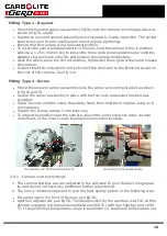
The voltage or range of voltages on which the furnace may be operated is given on the
furnace rating label. See fig 11a. Check that the electrical supply voltage is compatible
with the voltage on the label, and that the current capacity is sufficient for the maximum
current on the label before connection to the electrical supply.
The furnace should be permanently connected to the correct supply through a wall
mounted isolating switch or an easily removable plug. The switch or plug should be
within easy reach of the operator. Unless a supply cable is fitted the electrical supply
connections are to be made to terminals mounted inside back of the furnace, accessed
by removing the furnace back panel.
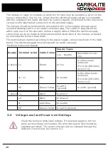
The terminals are marked according to the power supply, connect as shown in the table
below. The electrical supply must incorporate an earth (ground).
Supply
Terminal Label
Cable Colour
Supply Types
Live - Neutral
Reversible or Live-
Live
1-phase L1
Brown
to live
to either power
conductor
(For USA 200-240V,
connect L1)
N / L2
Blue
to neutral
to the other power
conductor
(For USA 200-240V,
connect L2)
PE
Green/ Yellow
to earth
(ground)
to earth (ground)
Electrical Connection Details:
2-phase L1
Black
to phase 1
L2
Black
to phase 2
N
Light Blue
to neutral
PE
Green/ Yellow
to earth (ground)
3.6
Voltage Level and Power Limit Settings
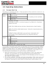
Check the furnace rating label voltage. If the actual supply is not the
same as the voltage on the label, the controller power limit should be
adjusted as follows. The power limit can also be changed through the
software if connected, see section 5.3.
16
Summary of Contents for CARBOLITE GERO CAF G5
Page 63: ...Fig 3 Front Tube Seal Assembly Fig 4 Door Arm Assembly 63 ...
Page 64: ...Fig 5a Camera Mounting Bracket Fig 5b Lens and Camera Assembly 64 ...
Page 65: ...Fig 5c Sliding the Camera Mounting Bracket Assembly onto the Door Arm 65 ...
Page 66: ...Fig 5d Securing the Camera Mounting Bracket Assembly to the Door Arm 66 ...
Page 67: ...Fig 5e Mounting the Lens and Camera Assembly 67 ...
Page 68: ...Fig 5f Lens and Camera Assembly in Position 68 ...
Page 69: ...Fig 6a Rear View of the Standard CAF G5 Furnace Showing Brick Box Assembly 69 ...
Page 71: ...Fig 7 Front Tube Seal Position 71 ...
Page 72: ...Fig 8 Tube End Seal Assembly Tightening Sequence Fig 9 Work Tube Front Support 72 ...
Page 73: ...Fig 10 Fitting the Door Arm Assembly Fig 10a Adjusting the Door Arm Assembly 73 ...
Page 74: ...Fig 11a Furnace Case and Controls 74 ...
Page 75: ...Fig 11b Gas Inlet Pipe Fig 12 Positioning the Furnace 75 ...
Page 77: ...Fig 13c Loading Samples into the Work Tube 77 ...
Page 78: ...Fig 16 File Folder 78 ...
Page 79: ...Fig 17 Door Arm Assembly Exploded View 79 ...
Page 82: ...SST DT HT FT Fig 18 Report Sheet Page 2 Side View Plan View Fig 19 Formed Wire Sample 82 ...
Page 83: ...Fig 20 Sample Carrier Sample Tiles and Sample Positions 83 ...
Page 84: ...Fig 21a Coal and Coke Test Piece Mould Fig 21b Biomass Test Piece Mould and Hand Press 84 ...
Page 85: ...Fig 22 Sample Loading Tool Fig 23 Camera Ethernet Connection 85 ...
Page 86: ...Fig 24 LED Driver Connection 86 ...
Page 87: ...Notes Service Record Engineer Name Date Record of Work ...

