


1 off
Furnace Assembly
1 off
Work tube and back seal assembly, see fig 2.
1 off
Work tube front insulating collar.
1 off
Work tube gasket.
1 off
Front tube seal assembly, see fig 3.
1 off
Door arm assembly (without door plug), see fig 4.
1 off
Door plug, see fig 4.
1 off
Flexible gas pipe.
1 off
Camera mounting bracket, see fig 5a.
1 off
Lens and camera assembly, see fig 5b.
6 off
Panel hole blanking plugs.
1 off
Sample Carrier.
1 off
Sample Loading Tool, see fig 21.
100 off
Sample tiles.
1 off
'Window retaining ring' spanner.
1 off
Cone mould.
1 off
1.25 mm Allen key
1 off
150 mm length of Gold wire (1063 °C fuse wire).
1 off
150 mm length of Palladium wire (1554 °C fuse wire).
1 off
Carbon Monoxide monitor
1 off
RS232 Interface cable.
1 off
Ethernet connection cable, Furnace/ Computer.
1 off
Computer.
1 off
Monitor.
1 off
Keyboard.
1 off
Mouse.
1 off
Memory Stick - containing a copy of the software and operation manual.
2 off
Computer power cable.
1 off
Installation, Operation and Maintenance Instructions for the CAF Test
Furnace.
3.3
Assembly of the Furnace
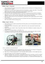
3.3.1
Element Fitting
Ensure that the furnace is isolated from the mains supply. Remove the back panel from
the furnace unit.
11
Summary of Contents for CARBOLITE GERO CAF G5
Page 63: ...Fig 3 Front Tube Seal Assembly Fig 4 Door Arm Assembly 63 ...
Page 64: ...Fig 5a Camera Mounting Bracket Fig 5b Lens and Camera Assembly 64 ...
Page 65: ...Fig 5c Sliding the Camera Mounting Bracket Assembly onto the Door Arm 65 ...
Page 66: ...Fig 5d Securing the Camera Mounting Bracket Assembly to the Door Arm 66 ...
Page 67: ...Fig 5e Mounting the Lens and Camera Assembly 67 ...
Page 68: ...Fig 5f Lens and Camera Assembly in Position 68 ...
Page 69: ...Fig 6a Rear View of the Standard CAF G5 Furnace Showing Brick Box Assembly 69 ...
Page 71: ...Fig 7 Front Tube Seal Position 71 ...
Page 72: ...Fig 8 Tube End Seal Assembly Tightening Sequence Fig 9 Work Tube Front Support 72 ...
Page 73: ...Fig 10 Fitting the Door Arm Assembly Fig 10a Adjusting the Door Arm Assembly 73 ...
Page 74: ...Fig 11a Furnace Case and Controls 74 ...
Page 75: ...Fig 11b Gas Inlet Pipe Fig 12 Positioning the Furnace 75 ...
Page 77: ...Fig 13c Loading Samples into the Work Tube 77 ...
Page 78: ...Fig 16 File Folder 78 ...
Page 79: ...Fig 17 Door Arm Assembly Exploded View 79 ...
Page 82: ...SST DT HT FT Fig 18 Report Sheet Page 2 Side View Plan View Fig 19 Formed Wire Sample 82 ...
Page 83: ...Fig 20 Sample Carrier Sample Tiles and Sample Positions 83 ...
Page 84: ...Fig 21a Coal and Coke Test Piece Mould Fig 21b Biomass Test Piece Mould and Hand Press 84 ...
Page 85: ...Fig 22 Sample Loading Tool Fig 23 Camera Ethernet Connection 85 ...
Page 86: ...Fig 24 LED Driver Connection 86 ...
Page 87: ...Notes Service Record Engineer Name Date Record of Work ...


