


7.0 Operation
7.0
Operation
7.1
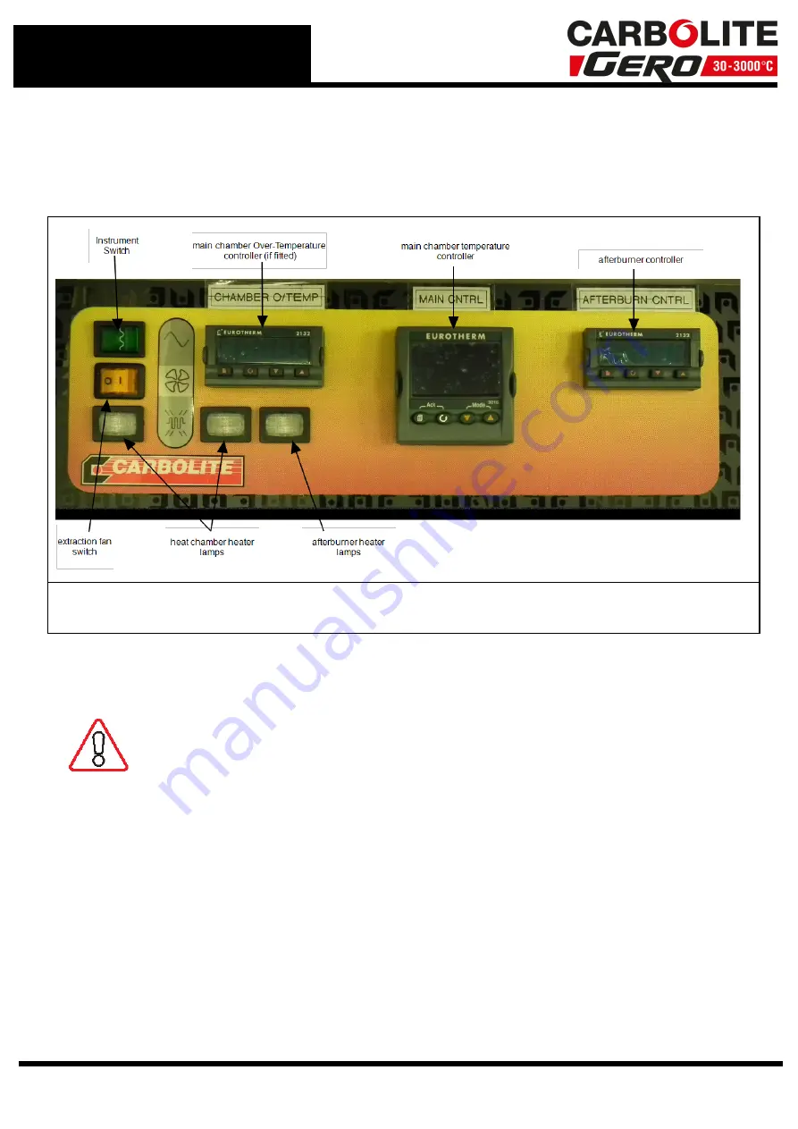
Switches - Control Panel
The main control switches are on the left hand side of the control panel (photo 3.1).
The Instrument Switch cuts off power to the controllers, other devices (including the
fan) and heating circuit contactors.
7.2
General Operating Notes
Heating element life is shortened by overheating. Do not leave the
product at high temperature when it is not required. The maximum
temperature is shown on the product rating label and in section 13.0
towards the back of this manual.
When heating large objects, in particular poor conductors, avoid shielding the
thermocouple from the heating elements. The thermocouple is intended to sense the
temperature near the heating elements. However, if a large object is placed in the
chamber it may record the average temperature of the object and the elements, this
can lead to overheating of the elements. Allow large objects to gain heat at a lower
temperature and then reset the controller to a temperature close to the desired
maximum, or heat using a slowly controlled ramp rate. For more information refer to
the controller instructions.
When heating materials that produce smoke or fumes, the chimney must be correctly
fitted and unobstructed. If not, soot will accumulate in the chamber and could possibly
cause an electrical breakdown of the heating element. If the furnace is used to heat
38
Summary of Contents for CARBOLITE GERO ABF 8/28
Page 11: ...Fig 14 Schematic for Mains Electrical Connections 11 3 0 Installation ...
Page 21: ...4 6 Navigation Diagram 21 4 0 2416 Controller ...
Page 33: ...5 7 Navigation Diagram 33 5 0 Afterburner 2132 Controller ...
Page 40: ...7 0 Operation Photo 3 5 40 ...
Page 53: ...Notes Service Record Engineer Name Date Record of Work ...


