USER’S MANUAL
VS
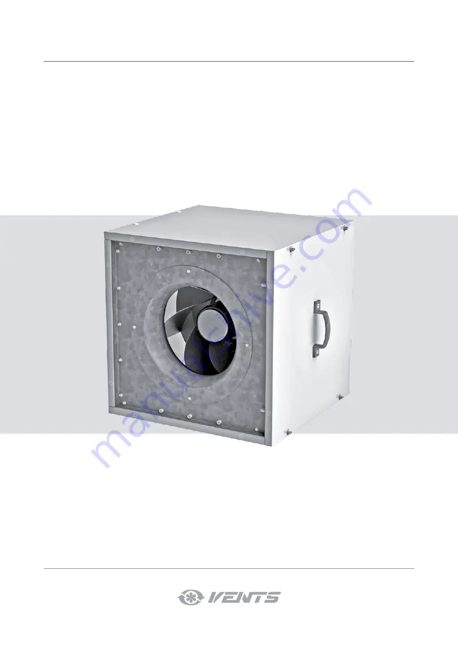
Duct centrifugal fan in sound insulated casing
Page 1: ...USER S MANUAL VS Duct centrifugal fan in sound insulated casing...
Page 2: ...eparation The Company reserves the right to modify the technical characteristics design or configuration of its products at any time in order to incorporate the latest technological developments No pa...
Page 3: ...the unit avoid compression of the casing Deformation of the casing may result in motor jam and excessive noise Misuse of the unit and any unauthorized modifications are not allowed Do not expose the...
Page 4: ...the latest technological developments No part of this publication may be reproduced stored in a retrieval system or transmitted in any form or by any means in any information search system or translat...
Page 5: ...The unit is rated for continuous operation The unit is a component part and is not designed for stand alone operation Transported air must not contain any flammable or explosive mixtures evaporation...
Page 6: ...55 40 60 40 60 Parameter VS 400 4D VS 450 4E VS 450 4D VS 500 4E VS 500 4D VS 560 4D Voltage V 3 400 Y 1 230 3 400 1 230 3 400 3 400 Frequency Hz 50 60 50 50 50 50 50 Power W 385 515 680 740 1300 143...
Page 7: ...1500 1440 1350 1540 1300 Sound pressure level at 3 m distance dBA 35 44 39 50 45 50 50 Transported air temperature 40 80 25 60 25 50 25 60 20 50 25 60 25 55 Model Dimensions mm H A B VS 315 355 500 31...
Page 8: ...0 460 225 75 KN VS 400 500 648 628 480 630 321 108 KN VS 560 630 778 758 610 760 421 141 KN VS 710 978 959 810 960 422 141 D h H A B C Options for fans Dimensions mm VPR VS A C D H VPR VS 315 355 600...
Page 9: ...h a maintenance free EC motor with an external rotor and an impeller with backward curved blades The fan has a special design that allows changing the position of the side panels for air supply in all...
Page 10: ...t diameter on the intake side and 3 air duct diameters on the exhaust side No filters or any other similar devices are allowed to be installed in these sections The fan is not a ready to use unit and...
Page 11: ...V GND 10 V 4 20 mA 4 20 mA 20 V KL3 X1 X1 QF KM1 KM1 L1 KM1 QF L1 L N X1 1 2 3 N L QF PE 230 V Hz 50 4 1 2 5 6 3 4 1 2 5 6 7 3 4 L N X1 N L QF PE 230 V Hz 50 TW1 TW2 TW1 TW2 TW1 TW2 TW1 TW2 TW1 TW2 T...
Page 12: ...hes 90 Fans with EC motors must be connected to the terminal block located in the external or integrated terminal box of the electric motor in strict accordance with the wiring diagram and terminal de...
Page 13: ...W1 TW2 TW1 TW2 TW1 TW2 TW1 TW2 TW1 TW2 TW1 TW2 W2 W1 V2 TW1 TW2 7 3 L3 L3 5 4 6 PE U2 8 9 0 10 V 0 10 V GND KL3 0 10 V 10 V KL3 KL3 0 10 V GND 10 V 4 20 mA 4 20 mA 20 V KL3 L N X1 X1 1 2 3 L QF N PE T...
Page 14: ...voltage slumps especially if the feed line section falls short of the requirements which may affect load operation The in rush current consumed by an electric motor in case of DOL starting is 5 8 tim...
Page 15: ...ent to maintain the induced current Typical symptoms Upon starting the circuit breakers at the system input are tripped the lights certain relays and contactors go off and the supply generator shuts d...
Page 16: ...s may result in damage to the winding or insulation due to overheating DURING STARTING THE IN RUSH CURRENTS OF THE FAN MAY SEVERAL TIMES EXCEED THE RATED VALUES SEE ASYNCHRONOUS ELECTRIC MOTOR STARTIN...
Page 17: ...ny mode of transport provided proper protection against precipitation and mechanical damage The unit must be transported only in the working position Avoid sharp blows scratches or rough handling duri...
Page 18: ...eller for warranty service The manufacturer s warranty does not apply to the following cases User s failure to submit the unit with the entire delivery package as stated in the user s manual including...
Page 19: ...CERTIFICATE The VS______________ unit is installed pursuant to the requirements stated in the present user s manual Installation Stamp Company name Address Phone Number Installation Technician s Full...
Page 20: ...V19EN 05...