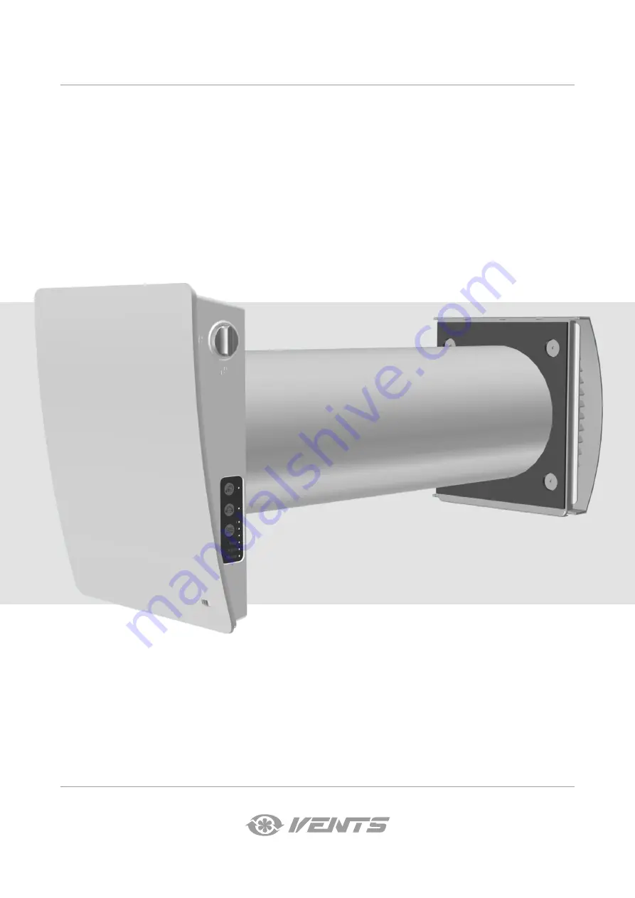
TwinFresh Style
TwinFresh Style Frost
TwinFresh Style M
TwinFresh Style Frost M
TwinFresh Style mini
TwinFresh Style mini M
Single-room reversible energy recovery ventilator
USER’S MANUAL
Page 1: ...TwinFresh Style TwinFresh Style Frost TwinFresh Style M TwinFresh Style Frost M TwinFresh Style mini TwinFresh Style mini M Single room reversible energy recovery ventilator USER S MANUAL...
Page 2: ...l requirements as well as the provisions of all the applicable local and national construction electrical and technical norms and standards must be observed when installing and operating the unit Disc...
Page 3: ...ysical sensory or mental capabilities or lack of experience and knowledge unless they have been given supervision or instruction concerning use of the appliance by a person responsible for their safet...
Page 4: ...erial 1 pc 1 pc Fan assembly 1 pc Regenerator assembly 1 pc Cartridge assembly 1 pc Outer ventilation hood 1 pc 1 pc Remote control 1 pc 1 pc Cardboard mounting plate 1 pc 1 pc Mounting kit 2 packages...
Page 5: ...ventilator are outside the specified limits turn off the ventilator Provide fresh air with open windows The unit is rated as a class II electric appliance Ingress protection rating against access to h...
Page 6: ...r use in colder climates VENTILATOR DESIGN DESIGN AND OPERATING PRINCIPLE Ventilation unit Generates air flow TwinFresh Style mini TwinFresh Style Regenerator unit Provides heat recovery Cartridge Con...
Page 7: ...particular ventilator starts operation depends on the position of DIP switch No 3 When installing two or an even number of ventilators they must be configured to operate in reverse phase While one ve...
Page 8: ...low A 165 mm A 370 mm A 310 mm Air duct length Wall thickness TwinFresh Style TwinFresh Style with a minimum wall thickness without fine filter holder and sound absorbing material TwinFresh Style mini...
Page 9: ...300 min 300 2 Insert the air duct in the wall For ease of installation use the mounting wedges included in the delivery set The air duct end must protrude for the distance A that enables installation...
Page 10: ...ning on the template Hole marking for unit fastening Entrance for wiring 103 23 160 75 106 72 152 71 136 144 5 Separate the front panel of the indoor unit from its back part To do this use a flat scre...
Page 11: ...e as figured below and connect the ventilator to power mains in compliance with the external wiring diagram see section Connection to power mains Secure the power cable with the clamp XP1 XP2 XP3 XP1...
Page 12: ...sound absorbing layer in the air duct Roll the layer of the sound absorbing material to match the air duct diameter The protecting paper layer must be outside Insert the sound absorbing roll into the...
Page 13: ...d A3 in compliance with the wiring diagram and terminal designation Connect the ventilator to power mains through an automatic circuit breaker with magnetic trip integrated into the home wiring system...
Page 14: ...s they must be connected to a single network All devices in the RS 485 network must be connected using the Bus topology There can be only one ventilator with the Master setting and up to 15 ventilator...
Page 15: ...tation direction 3 ON in the Ventilation mode the ventilator supplies the air to the room in the Regeneration mode the ventilator starts operating first in the supply mode 3 OFF in the Ventilation mod...
Page 16: ...or unit The speed selection sequence is as follows I II III Standby All the units integrated in a single network operate according to the speed settings of the Master unit I permanent indicator glowin...
Page 17: ...to the Master unit No glowing of the lamp indicator means that this ventilation unit is a Slave ventilation unit and it is connected to a Master unit Description of the buttons on the remote control...
Page 18: ...wer supply completely 1 Remove the front part of the indoor control unit as shown in step 5 of the Mounting and Set up section Move the air damper to the open position using the handle 2 Disconnect th...
Page 19: ...even in case of regular maintenance of the filters Clean the regenerator regularly to ensure its high heat recovery efficiency Vacuum clean the regenerator not less than once a year 4 Replacement of t...
Page 20: ...r up after transportation at low temperatures allow the unit to warm up at operating temperature for at least 3 4 hours POSSIBLE REASONS AND TROUBLESHOOTING Problem Possible reasons Troubleshooting Wh...
Page 21: ...ler for warranty service The manufacturer s warranty does not apply to the following cases User s failure to submit the unit with the entire delivery package as stated in the user s manual including s...
Page 22: ...22 TwinFresh Style mini Frost M www ventilation system com...
Page 23: ...FICATE TheTwinFresh Style _____________ unit is installed pursuant to the requirements stated in the present user s manual Installation Stamp Company name Address Phone Number Installation Technician...
Page 24: ...V222 2EN 02...