background image

5

www.ventilation-system.com

The unit is designed for indoor application with the ambient temperature ranging from +1 °C up to +40 °C and relative humidity up to 
80 % at 25 °C.
The maximum permissible concentration of solids and dust in the handled air is 10 mg/m3.
The unit is rated as a Class I electrical appliance.
The unit design is constantly being improved, thus some models may be slightly different from those described in this manual.

TECHNICAL DATA

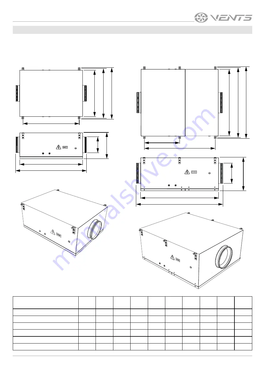
Weight and overall and connecting dimensions of the fan unit [mm]

Model

L

L1

L2

L3

H

A

A1

A2

ØD

Weight 

[kg]

DuoVent 150 EC

975

850

748

321

621

593

540

149

28

DuoVent 200 EC

975

850

748

375

791

763

710

199

39

DuoVent 250 EC

1102

979

877

417

801

773

720

249

53

DuoVent 315 EC

1293

1170

1068

534

520

1092

1065

1010

314

97

DuoVent 355 EC

1334

1170

1068

534

520

1092

1065

1010

354

97

DuoVent 400 EC

1358

1194

1092

546

551

1182

1154

1101

399

129

L2

A2

A1

A

ØD

H

L1

L

L2

L3

A2

A1

A

ØD

H

L1

L

Summary of Contents for DuoVent 150 EC

Page 1: ...DuoVent 150 EC DuoVent 200 EC DuoVent 250 EC DuoVent 315 EC DuoVent 355 EC DuoVent 400 EC Duct redundancy fan unit in a sound insulated casing USER S MANUAL ...

Page 2: ...nd maintain ventilation units Do not attempt to install the product connect it to the mains or perform maintenance yourself This is unsafe and impossible without special knowledge Disconnect the power supply prior to any operations with the unit All user s manual requirements as well as the provisions of all the applicable local and national construction electrical and technical norms and standard...

Page 3: ...ced physical sensory or mental capabilities or lack of experience and knowledge if they have been given supervision or instruction concerning use of the appliance in a safe way and understand the hazards involved Cleaning and user maintenance shall not be made by children without supervision Children shall not play with the appliance Connection to the mains must be made through a disconnecting dev...

Page 4: ...ed space for mounting The fan unit is a component part and cannot be used for stand alone operation It is rated for continuous operation Transported air must not contain any flammable or explosive mixtures evaporation of chemicals sticky substances fibrous materials coarse dust soot and oil particles or environments favourable for the formation of hazardous substances toxic substances dust pathoge...

Page 5: ... models may be slightly different from those described in this manual TECHNICAL DATA Weight and overall and connecting dimensions of the fan unit mm Model L L1 L2 L3 H A A1 A2 ØD Weight kg DuoVent 150 EC 975 850 748 321 621 593 540 149 28 DuoVent 200 EC 975 850 748 375 791 763 710 199 39 DuoVent 250 EC 1102 979 877 417 801 773 720 249 53 DuoVent 315 EC 1293 1170 1068 534 520 1092 1065 1010 314 97 ...

Page 6: ...6 DuoVent 150 200 250 315 355 400 EC www ventilation system com Technical specifications of the particular model are indicated on the unit casing ...

Page 7: ...l automatics the fans can be switched on alternately at different time intervals This ensures uninterrupted ventilation in case of failure of one fan the second one automatically switches on Switching modes is carried out using a controller which is not included in the basic delivery set and must be ordered separately In order to prevent air backflow through a non functioning fan a swivel damper i...

Page 8: ... section Fasteners for unit mounting should be selected by the service technician The safety cables on the removable service panels can be moved to the opposite side of the casing for the convenience of service work depending on the installation location of the fan unit MOUNTING AND SET UP WHILE INSTALLING THE UNIT ENSURE CONVENIENT ACCESS FOR SUBSEQUENT MAINTENANCE AND REPAIR BEFORE MOUNTING MAKE...

Page 9: ...ion method The external power input must be equipped with an automatic circuit breaker built into the stationary wiring to open the circuit in the event of overload or short circuit The position of the external circuit breaker must ensure free access for quick unit power off The trip current of the automatic circuit breaker must exceed the maximum current consumption of the unit refer to the Techn...

Page 10: ...DuoVent 250 EC DuoVent 315 EC DuoVent 355 EC DuoVent 400 EC GND 0 10V N L TACH 10V GND 0 10V TACH 10V GND 0 10V TACH 10V GND 0 10V TACH 10V N L 10V CTR X2 TACH GND 10V CTR TACH GND N L 2 X1 QF N L Red White Yellow Blue External control device 1 220 240 V Blue Brown 10V CTR X2 TACH GND 10V CTR TACH GND N L N L X1 QF Red White Yellow Blue External control device 1 220 240 V Blue Brown Yellow green ...

Page 11: ...ECTION AVOID LIQUID SPILLS ON THE MOTOR DO NOT USE AGGRESSIVE SOLVENTS AND SHARP OBJECTS FOR CLEANING PRIOR TO COMMENCING ANY TECHNICAL MAINTENANCE PUT UP A PROHIBITORY SIGN ON THE FAN STARTING PANEL DO NOT SWITCH ON MEN AT WORK TECHNICAL MAINTENANCE TROUBLESHOOTING Problem Possible reasons Troubleshooting The fan s doesn t don t start No power supply Make sure the power supply line is connected c...

Page 12: ...Use suitable hoist machinery for handling and storage operations to prevent possible damage to the unit Follow the handling requirements applicable for the particular type of cargo The unit can be carried in the original packaging by any mode of transport provided proper protection against precipitation and mechanical damage The unit must be transported only in the working position Avoid sharp blo...

Page 13: ...tling unit setup To benefit from warranty repair the user must provide the unit the user s manual with the purchase date stamp and the payment paperwork certifying the purchase The unit model must comply with the one stated in the user s manual Contact the Seller for warranty service The manufacturer s warranty does not apply to the following cases User s failure to submit the unit with the entire...

Page 14: ...14 DuoVent 150 200 250 315 355 400 EC www ventilation system com ...

Page 15: ...ATE The _____________________________________ unit is installed pursuant to the requirements stated in the present user s manual Installation Stamp Company name Address Phone Number Installation Technician s Full Name Installation Date Signature The unit has been installed in accordance with the provisions of all the applicable local and national construction electrical and technical codes and sta...

Page 16: ...V256EN 03 ...

Reviews: