���������������
��������
�� ���
�������������
������������������������������������
������������������������������������������
Page 1: ......
Page 2: ......
Page 3: ...ectrical connections Page 33 Glossary Page 34 Operation Page 39 Setting the regulation parameters Page 39 Parameter menu Page 41 Error messages Page 48 Reference standards Page 49 Dimensions and conne...
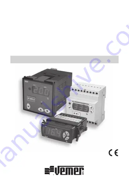
Page 4: ...regulators satisfying the simplest requirements in the field of heat regulation They can be used as heating or refrigeration regulators and as maximum minimum alarms Three dedicated base models for p...
Page 5: ...regulation ON OFF selection of probe to be displayed set point switching direct reverse switching etc Acoustic and visual alarm signals for outside alarm from digital input probe alarm malfunction min...
Page 6: ...YES YES VM643400 HT JK 2P3D from 12 to 24 V AC DC 10 2 YES YES Rear panel 72x72 mm Code Model Power supply Power supply n of Digital Infrared tollerance relays input receiver VM625100 HT NiPt 1P7A 24...
Page 7: ...ting to become ON due to an active timing Out 2 LED off if relay two is OFF on if relay two is ON flashing if relay two in OFF is waiting to become ON due to an active timing Keys Three parameter sett...
Page 8: ...ucing the temperature Reverse action A regulator acts in reverse mode when it limits the reduction of the measurement controlled For example in a heating system the reduction in temperature correspond...
Page 9: ...point If both outputs are used the hysteresis for each output is equivalent to half the differential In this case output 1 will be activated when the measurement controlled reaches the value ST1 DF1...
Page 10: ...or both outputs In this operating mode the relays are activated impulsively with an interval that can be set on the basis of the TCL value see the output menu Within this interval the relay will stay...
Page 11: ...fferential 1 if the digital input is open and set point 2 differential 2 if closed The operating modes are the same as mode 0 It is necessary to set both the set point ST1 and ST2 differential DF1 and...
Page 12: ...and differential 2 PRO 9 respectively In this mode output 1 operates in reverse and output 2 in direct It is necessary to set the values of set point 1 ST1 and differential 1 DF1 for output 1 and set...
Page 13: ...sor The status of outputs OUT1 and OUT2 There are two types of programming for the setting of the regulation parameters Simplified programming Advanced programming Note to reset the default values set...
Page 14: ...entered correctly the label of the first menu will appear Otherwise the system will return to normal status Advanced programming Access is gained to advanced programming from normal status by pressin...
Page 15: ...ing the changes made Note During the display and modification of the parameters the instrument will continue to operate with the previously set parameters If password 2 is enabled access password for...
Page 16: ...onnected to the instrument this parameter is frequently used for compressors for example 5 the minimum time for which the output should remain ON 6 timing enabled for relay 1 output only OFF Labels of...
Page 17: ...S1 contact open probe S0 contact closed probe S1 The digital input function is excluded when one of the following operating modes is selected inside the system menu SYS mode 6 mode 7 and mode 8 10 Thi...
Page 18: ...ent unit is modified the parameters set are not con verted automatically but have to be re calibrated Labels of parameters that can be modified Description Parameter values default notes SUA Output st...
Page 19: ...t to this parameter by default It corresponds to the use of temperature sensor NTC code VN870200 see Red Line catalogue under the item Heat Regulation Temperature Probes For the use of sensors other t...
Page 20: ...ft of the set point 2 neutral zone with channel 1 in reverse and channel 2 in direct with set point 1 and differential 1 3 as mode 0 but with differential centred on the set point 4 as mode 1 but with...
Page 21: ...switching between set point 1 differential 1 and set point 2 differential 2 through digital input open set 1 closed set 2 5 output associated with maximum alarm for set point 2 6 output associated wit...
Page 22: ...ating mode Parameter 0 1 2 3 4 5 6 7 8 9 10 IN0 50 50 100 0 0 100 50 50 100 100 DF0 50 50 100 50 50 100 50 50 100 100 IN1 100 100 100 50 50 100 100 100 100 0 DF1 50 50 100 50 50 100 50 50 100 100 The...
Page 23: ...49 User Manual Digital Heat Regulators English For safety EN 60730 2 9 For electromagnetic compatibility EN 55014 1 EN 55014 2 EN 61000 6 2 EN 61000 6 3 REFERENCE STANDARDS English...
Page 24: ...e r s up p l y Relay output 8 1 A 250 V Digital input Probe input PTC 3 wires Probe input PTC 2 wires Digital input 6 7 8 9 5 2 3 4 1 6 7 8 9 Connection diagram Model HT NiPt 1P3D HT NTC 1P3D HT JK 1P...
Page 25: ...put 2 8 1 A 250 V Probe input PTC 3 wires Probe input PTC 2 wires Digital input Relay output 1 8 1 A 250 V Relay output 2 8 1 A 250 V Digital input 14 11 12 13 15 10 16 17 18 5 2 3 4 6 1 7 8 9 16 17 1...
Page 26: ...5 10 16 17 18 HT JK 1P3A Probe input TC Digital input Relay output 8 1 A 250 V P o wer sup p ly 14 11 12 13 15 10 16 17 18 5 2 3 4 6 1 7 8 9 HT JK 1P3D Probe input TC Digital input Relay output 8 1 A...
Page 27: ...HT NiPt 1P7A 24 V 5 0 60 H z 230 V 5 0 60 H z Relay output 8 1 A 250 V Probe input PTC 3 wires Probe input PTC 2 wires 4 5 6 1 2 7 11 12 1 4 5 6 HT NiPt 2P7A 24 V 5 0 60 H z 230 V 5 0 60 H z Relay out...
Page 28: ...6 0 H z 230 V 5 0 6 0 H z NTC1 NTC2 Probe input NTC Relay output 1 8 1 A 250 V Relay output 2 8 1 A 250 V 4 5 6 1 2 3 8 9 7 11 12 10 HT JK 1P7A 24 V 5 0 6 0 H z 230 V 5 0 6 0 H z Probe input TC Relay...
Page 29: ...60 H z 230 V 5 0 60 H z Digital input Probe input PTC 3 wires Probe input PTC 2 wires Relay output 8 1 A 250 V 5 2 3 4 6 1 14 11 12 13 15 10 7 16 8 9 17 18 16 17 18 HT NiPt 2DA 24 V 5 0 60 H z 230 V 5...
Page 30: ...input Probe input NTC NTC1 NTC2 Relay output 1 8 1 A 250 V Relay output 2 8 1 A 250 V 5 2 3 4 6 1 14 11 12 13 15 10 7 16 8 9 17 18 HT JK 1DA 24 V 5 0 60 H z 230 V 5 0 60 H z Digital input Probe input...
Page 31: ......
Page 32: ...ale di Brugherio I 20047 Brugherio Mi Via Belvedere 11 Phone 39 039 20901 Fax 39 039 2090222 www vemersiber it V3IS00323 010 122006 Vemer S p A I 32032 Feltre BL Via Camp Lonc 16 Tel 39 0439 80638 Fax...