PC FUNCTION GENERATOR
Velleman PCG10 DIAGRAMS AND CALIBRATION
Page 1: ...PC FUNCTION GENERATOR Velleman PCG10 DIAGRAMS AND CALIBRATION ...
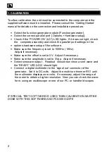
Page 2: ...heck the parallel port settings in the options hardware setup of the software Make sure the frequency is set to 1000Hz 1KHz Adjust if necessary Make sure the offset is set to 0V Adjust if necessary Make sure the amplitude is set to 5Vpp Adjust if necessary Select sinewave output Readout should now show a sine wave and the READY LED LD2 should light Connect a digital multimeter to the signal out co...
Page 3: ...2 PCB Component side ...
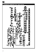
Page 4: ..._______________________________________________________________________________________________________________________________________________________ 4 3 SCHEMATIC DIAGRAM Power supply section ...
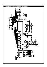
Page 5: ...4 SCHEMATIC DIAGRAM Analogue section ...
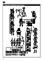
Page 6: ..._______________________________________________________________________________________________________________________________________________________ 6 5 SCHEMATIC DIAGRAM Digital section ...