


Total solder points: 83
Difficulty level:
beginner
1
o
2
þ
3
o
4
o
5
o
advanced
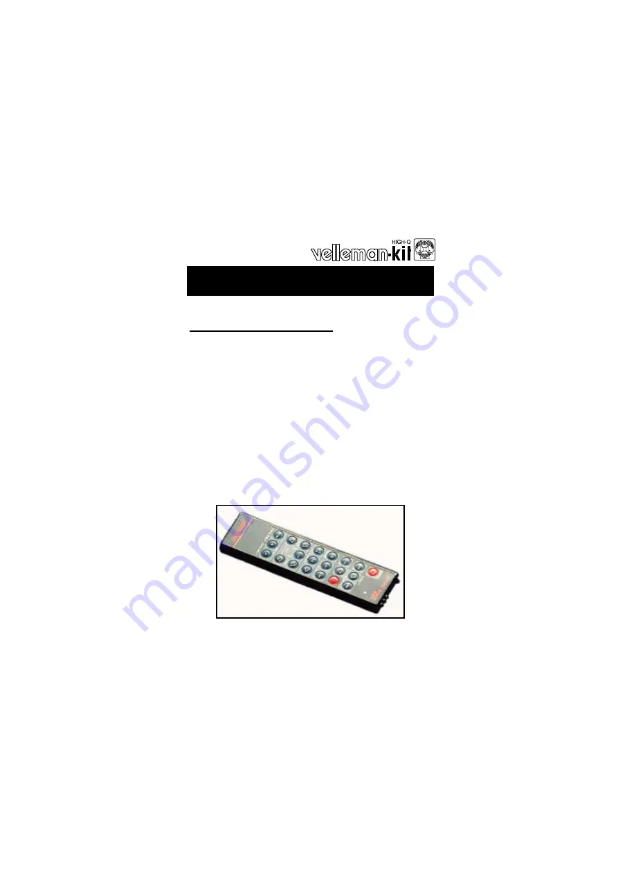
K4101 / K6710
15 Channel infrared transmitter
ILLUSTRATED ASSEMBLY MANUAL H6710IP-ED1
þ
Tactile Keyboard.
þ
Complete with aluminium Housing.
þ
Transmitter carrier wave frequency : 38KHz.
þ
Number of identification codes : 6
þ
15 independent channels.
þ
Standby current consumption : 0.1 µA.
þ
Average current consumption during transmission : 10mA.
Works together with :
Ø
K6711 - 15 Channel infrared receiver.
Ø
K6712/13 One Channel infrared receiver.
Ø
K4100 Digital controlled preamplifier.
Ø
K4500 digital synthesizer FM tuner.
þ
Power supply : 9V Battery (not included).
þ
Dimensions : 50 x 23 x 175mm (2” x 0,9” x 6,9”).
Modification reserved
Features and specifications :