Velleman DK-2800 Installation & Operation Manual Download Page 1

SPLIT-DECODED CONTROLLER

FOR DK-2800 SECURITY KEYPADS
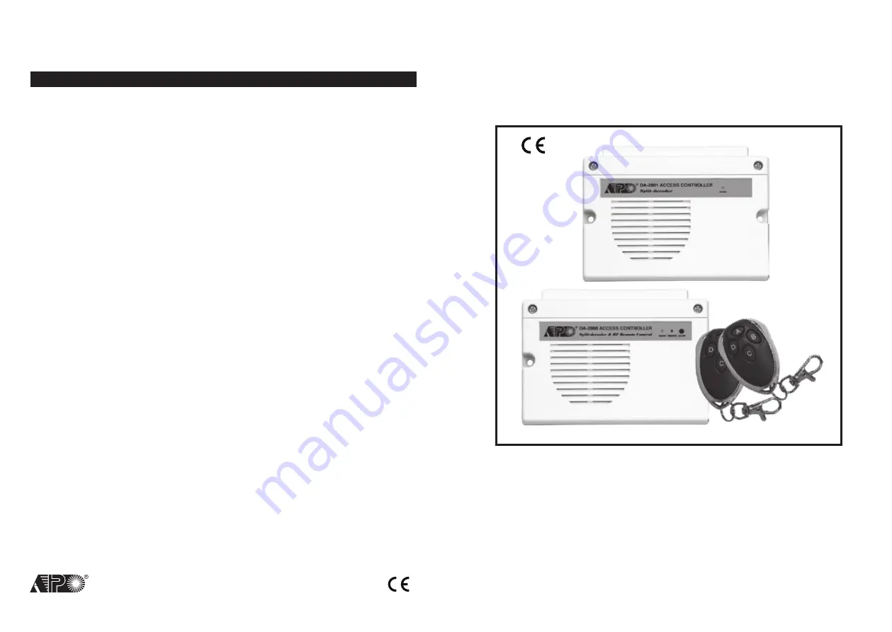
DA-2800 & DA-2801

Installation & Operation Manual

FOR ELECTRIC LOCK, INTER-LOCK

AND SECURITY SYSTEM INSTALLATIONS

VERSION: 10/2010

AEI PROTECT-ON SYSTEMS LIMITED

www.apo-hk.com

RoHS

Compliance

FCC STATEMENT


1

.

 This device complies with Part 15 of the FCC Rules

.


Operation is subject to the following two conditions:

(1)This device may not cause harmful interference, and

(2)This device must accept any interference received, including interference  

that may cause undesired operation.

2. Changes or modifications not expressly approved by the party responsible for

compliance could void the user's authority to operate the equipment.

Summary of Contents for DK-2800

Page 1: ...liance FCC STATEMENT 1 This device complies with Part 15 of the FCC Rules Operation is subject to the following two conditions 1 This device may not cause harmful interference and 2 This device must accept any interference received including interference that may cause undesired operation 2 Changes or modifications not expressly approved by the party responsible for compliance could void the user ...

Page 2: ...2 3 3 3 3 41 8 0 Door Forced Open Warning Time FUNCTION MODE TIME 0 OFF 1 999 Seconds 80 FUNCTION TIME Mode 0 Door Forced Open Warning OFF 8 1 Propped up Warning Time 81 FUNCTION TIME Mode 0 Propped up Warning OFF 9 0 Egress Delay Warning Alarm CODE 1 FUNCTION MODE 1 Momentary No warning 2 Momentary with warning 3 Momentary with warning Alarm 4 Hold Contact No warning 5 Hold Contact with warning 6...

Page 3: ...etion of User PIN CODE 2 USER ID 000 999 Group 1 10 001 100 Group 2 20 001 100 Group 3 30 CODE 3 USER PINs Cards 4 8 Digits Cards 10 CODE1 CODE2 CODE3 NIL 2 0 User PINs Cards for O P 2 20 CODE1 CODE2 CODE3 NIL 3 0 User PINs Cards for O P 3 30 CODE1 CODE2 CODE3 NIL 4 0 Visitor Codes CODE 1 VISITOR ID 01 50 CODE 2 VALID PERIOD 00 One Time 01 99 Hours CODE 3 VISITOR CODE 4 8 Digits 40 CODE1 CODE2 COD...

Page 4: ...utside II DA 2800 Only Provides The Tri Tech Features of RF Remote Control Card and PIN Code Reading in One System 24 bits Self learning Codes over 1 million codes for The RF Remote Control Keys Accepts 40 RF Remote Control Keys Maximum 4 RF Remote Control Channels for Stand Alone or Split decoded Operation Remote Control Key Controls Output 1 2 3 Door Chime 4 CLOSE THE PROGRAMMING MODE Always clo...

Page 5: ... beep 90 5 10 a b c d a Egress function programming b Holding contact mode with warning c Holding time of 10 seconds to release door d Entry confirmation Example 3 Set Egress Button in Momentary contact without delay This is the default setting 90 1 0 a b c d a Egress function programming b Momentary contact without delay c Release door instantly d Entry confirmation DOOR OPENING ALARM TIMER Locat...

Page 6: ...the Keypad without triggering of the Buzzer and Alarm Output 4 Holding Contact Mode without Warning Press and hold the Button No warning or alarm is given during the Egress Delay Good for the silent area The people require to press hold the button until the delay time reaches for the door open 5 Holding Contact Mode with Warning Beep Press and hold the Button The system gives Warning Beeps during ...

Page 7: ...h warning for the delay and even gives alarm when a controlled door is opened Locations 90 and 91 below are the places for setting the desired functions for the Egress Button The functions programmed to the Egress Button do not affect the normal operation of the system with its keypad For the safety consideration the operation of the keypad with PIN Code or Card is always in the first priority to ...

Page 8: ...Master keypad at the first time it is necessary to let the decoder unit to know the Master Code of the keypad Otherwise the decoder can not recognize the data from it If more than one keypads are going to link up with the decoder all the keypads are required to have the same Master Code and repeat link up is not necessary The decoder executes Link up Acquisition Only Once at the moment after setti...

Page 9: ...ton C on the remote key is pressed and it stops when the button is released ENTRY MODES VALIDATION LOCATION 1 or 2 70 USER PIN ENTRY MODE Auto or Manual Location 70 USER PIN ENTRY MODES Two modes 1 and 2 are available for User PIN entry options The EM Card is always in Auto Entry Mode and is not affected by the selection here 1 Auto Entry Mode Auto Entry Mode requires no pressing of the key follow...

Page 10: ...ntrol alarm arm disarm control they are also universal timers for automatic operators in industry with their 99 999 seconds over 24 hours programmable timer OUTPUT LOCATIONS 51 Location for Output 1 52 Location for Output 2 53 Location for Output 3 OUTPUT MODE TIMING 0 Start Stop Mode Toggle The number 0 sets the output to the Start Stop mode The output Starts when an User PIN and or Card is enter...

Page 11: ...e doors is opened the other door keeps close until the open door is re closed It prevents the unauthorized people dashing into a protected area An inter lock system needs two keypads or controllers and two door position sensing switches for the two doors Please see the Application Example for more information 9 O P 1 INHIBIT Output 1 Inhibit Control Input Normally Open A Normally Open N O sensing ...

Page 12: ...Function Jumper on position 2 or Adjustable Momentary Timer mode with Function Jumper on position 3 in Stand Alone mode The Adjustable Timer 1 30 seconds is located on the main circuit board inside the box See Figure 2 16 17 18 OUTPUT 2 Output Relay 2 1 Amp relay dry contact controlled by the Group 2 User PINs Cards in Split decoded mode or by the RF remote key in Stand Alone mode It is an auxilia...

Page 13: ...onfirms the reading and 30 seconds waiting time is given for the entry of the Duress Code the Amber LED keeps flashing b Key in one of the Duress Codes for the specific output the Code programmed in Location 41 42 or 43 for Output 1 2 and 3 respectively c Confirm it with the key The specific Output activates in a normal way and the Duress Output also activates to report Duress Event to an alarm sy...

Page 14: ...rogramming 10 4 003 a b c d e a The card is programmed for operating of the Output 1 b The operation is EM Card Common User PIN c Take ID number 003 in Group 1 to store the card which is one of the IDs in 000 999 d Put the card close to the reader One beep confirms the reading No need to key in a Common User PIN but there MUST be a Common User PIN already recorded in Location 03 or 04 05 if for O ...

Page 15: ...ess button C to operate Output 3 4 Press button D to operate the built in Door Chime STAND ALONE MODE DA 2800 ONLY The system that operates in Stand Alone mode does not require the keypad It is directly controlled by the RF Remote Key for the outputs It is an ideal solution for the remote controls of door strike alarm arm disarm garage door opening etc The following settings are necessary while th...

Page 16: ... Output 3 100 Users are allowed in group 3 for O P 3 SELECTION OF OPERATION MEDIA Number 1 2 3 or 4 represents the Media to be used to operate the keypad Number 5 is the authorization code for deleting of an PIN and or Card from its User ID EM Card only Private User PIN only EM Card Secondary User PIN EM Card Common User PIN Delete an User PIN or Card from the selected User ID number Clear all the...

Page 17: ... Output 2 Resets Output 3 Activates or Output 3 Resets 2 Inhibit The User PINs For Output 1 The Super User PIN can also be used to inhibit the normal User PINs Cards for the Output 1 usually they are for door strike It enhances the security level of the access control system such as to stop a keypad after office hour or while the house is nobody inside Once the Output 1 is inhibited the User PINs ...

Page 18: ...n 80 and Location 91 for more information about these functions Only one connection option is recommended Make sure that the sink current does not exceed the maximum rating of 100mA C ALARM OUTPUT GND N C TAMPER SWITCH OF THE KEYPAD GND DOOR SENS 18 ALARM O P KEY ACT O P GND ALARM O P KEY ACT O P GND Example User Name Location Function Code User ID PIN Code Card Remark 1 2 3 4 5 6 7 8 9 10 11 12 1...

Page 19: ...ong beep is given if a Code PIN is keyed in or a Card is read It means that a Prime Code or a Prime Card is repeated The Code PIN or Card was already in one of the PIN or Card Locations or IDs The programming is invalid Change a new Code PIN or Card and program it again d Secondary User PINs The Secondary User PINs are prepared to enhance security It is put after a Card in EM Card Secondary User P...

Page 20: ... 0 1 Master Code 0 0 0 0 Factory Set Not a default value 0 2 Super User PINs Nil User Program Required 0 3 Common User PIN 1 Nil User Program Required 0 4 Common User PIN 2 Nil User Program Required 0 5 Common User PIN 3 Nil User Program Required 1 0 User PINs Cards for O P 1 Nil User Program Required 2 0 User PINs Cards for O P 2 Nil User Program Required 3 0 User PINs Cards for O P 3 Nil User Pr...

Page 21: ...unctions in the keypads with Door Bell button It is a door bell button while the keypad is in normal operation and it is equivalent to a Button in programming mode MASTER CODE The Master Code can be a factory set master code or the private master code that was set by the owner Validate the master code with or 2 beep confirms a valid master code The Mains LED Amber is constantly ON after the system...

Reviews: