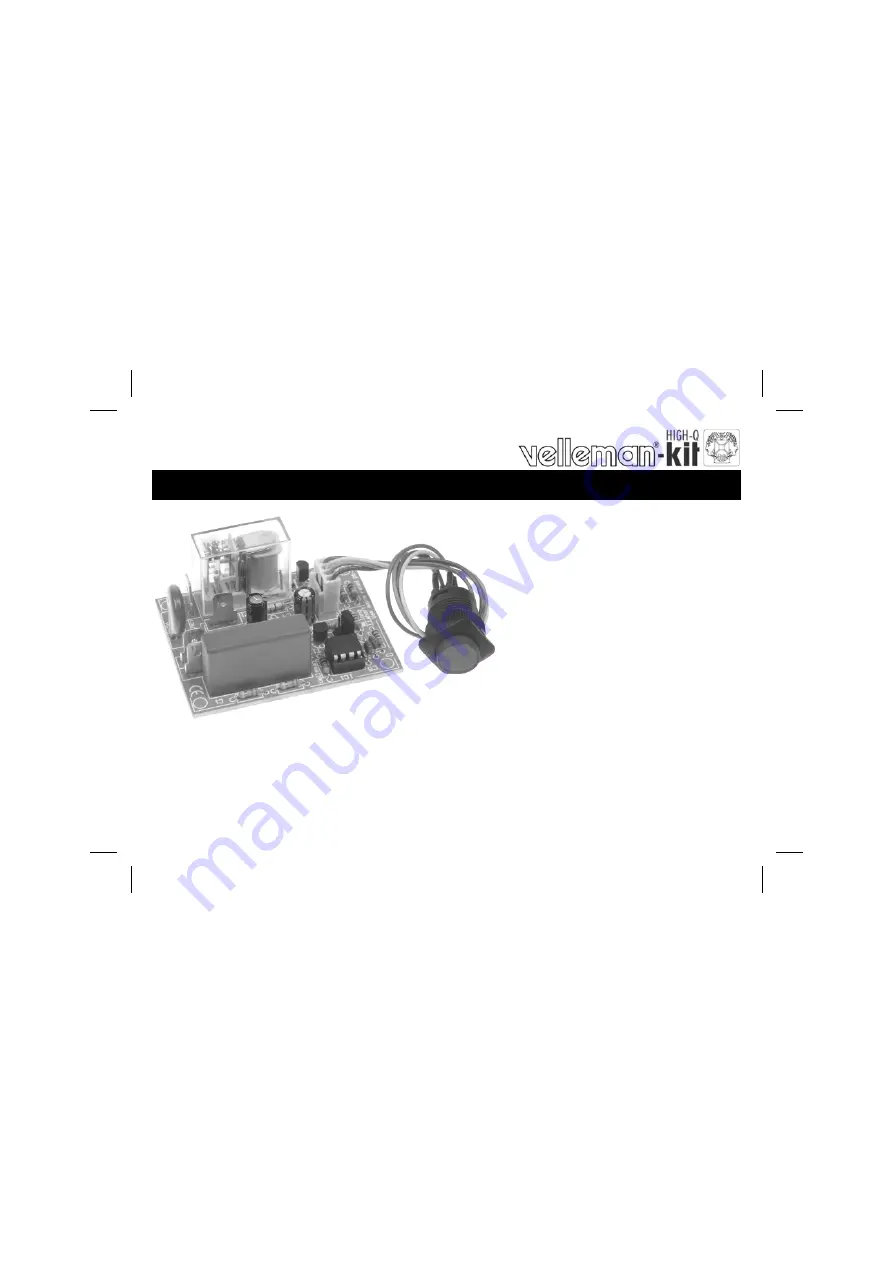
POWER SAVER / TIMER
K8075
ILLUSTRATED ASSEMBLY MANUAL
H8075IP-1
Total solder points: 202 Difficulty level:
beginner
1
2
3
4
5
advanced
Turns o
ff your e
quipme
nt after
a prese
t time, i
t
helps y
ou save
money
and it i
ncrease
s safety
Page 1: ...TIMER K8075 ILLUSTRATED ASSEMBLY MANUAL H8075IP 1 Total solder points 202 Difficulty level beginner 1 2 3 4 5 advanced Turns off your equipment after a preset time it helps you save money and it incre...
Page 2: ......
Page 3: ...h or 8h turn off timer fast flashing 1h or 2h turn off timer dim idle Choose short or long running timers one time jumper setting 10A suppressed relay output Easy to add to existing equipment Applicat...
Page 4: ...he eyes Needle nose pliers for bending leads or to hold components in place Small blade and Phillips screwdrivers A basic range is fine For some projects a basic multi meter is required or might be ha...
Page 5: ...ke sure the solder joints are cone shaped and shiny 3 Trim excess leads as close as possible to the solder joint REMOVE THEM FROM THE TAPE ONE AT A TIME AXIAL COMPONENTS ARE TAPED IN THE CORRECT MOUNT...
Page 6: ...0 2K2 2 2 2 B R11 6K8 6 8 2 B R12 3K9 3 9 2 B 5 Resistors IC1 8p 6 IC socket Watch the position of the notch Construction D1 1N4148 1 Diodes Watch the polarity 4 Metal film resistors 1 R ZD1 5V1 0 5W...
Page 7: ...1 2p 10 Pin header Choose timer Mounted 2h 8h Not mounted 1h 4h 11 Shunt VDR1 VDR300 13 VDR L N L N 12 PCB terminals T1 BC547B T2 BC547B 8 Transistors AC power out AC power in C3 100 F 35V C4 100 F 35...
Page 8: ...10V241C 24DC 10A 1contact 16 Relays IC1 VK8075 programmed PIC10F200 I PG 17 IC Watch the position of the notch CHECK THOROUGHLY ALL THE COMPONENTS FOR MISS MOUNTING INCLUDING SOLDERING ERRORS PUT AN E...
Page 9: ...ow to check the accuracy of the connections see figure 3 0 Attention Always make sure to slide down the shrinking tube far enough from the soldering points Slide the shrinkable tube over the soldered...
Page 10: ...o use a different push button make sure it is rated for the AC voltage If you do not use the included push button you can mount a 3mm LED on the PCB COLOR 2 5 LD CATHODE Watch the polarity Do not use...
Page 11: ...MIGHT APPLY MOUNT THIS KIT PREFERABLY IN AN ISOLATED ENCLOSURE Connect your application ex lamp to the unit Lout N Connect the power supply to the power connections of the PCB L N see fig 4 0 Warning...
Page 12: ...Long term timer Mount the jumper JP1 At power on the pushbutton LED or LD1 will flash slowly twice hereby indicating that long term timers have been selected 2h or 8h turn off timer 2 Short term timer...
Page 13: ...setting of jumper JP1 Pushbutton LED or LD1 blinks fast Long turn off delay 2h or 8h depending on setting of jumper JP2 Pushbutton LED or LD1 blinks slowly Hold button for 2 3s turn on relay and activ...
Page 14: ...14 20 Schematic diagram Diagram...
Page 15: ...15 21 PCB PCB...
Page 16: ...ions and typographical errors reserved Velleman Components nv H8075IP 2005 ED1 VELLEMAN Components NV Legen Heirweg 33 9890 Gavere Belgium Europe www velleman be www velleman kit com 5 4 1 0 3 2 9 3 4...