Velbus VMB8PBU Extended Manual Download Page 1


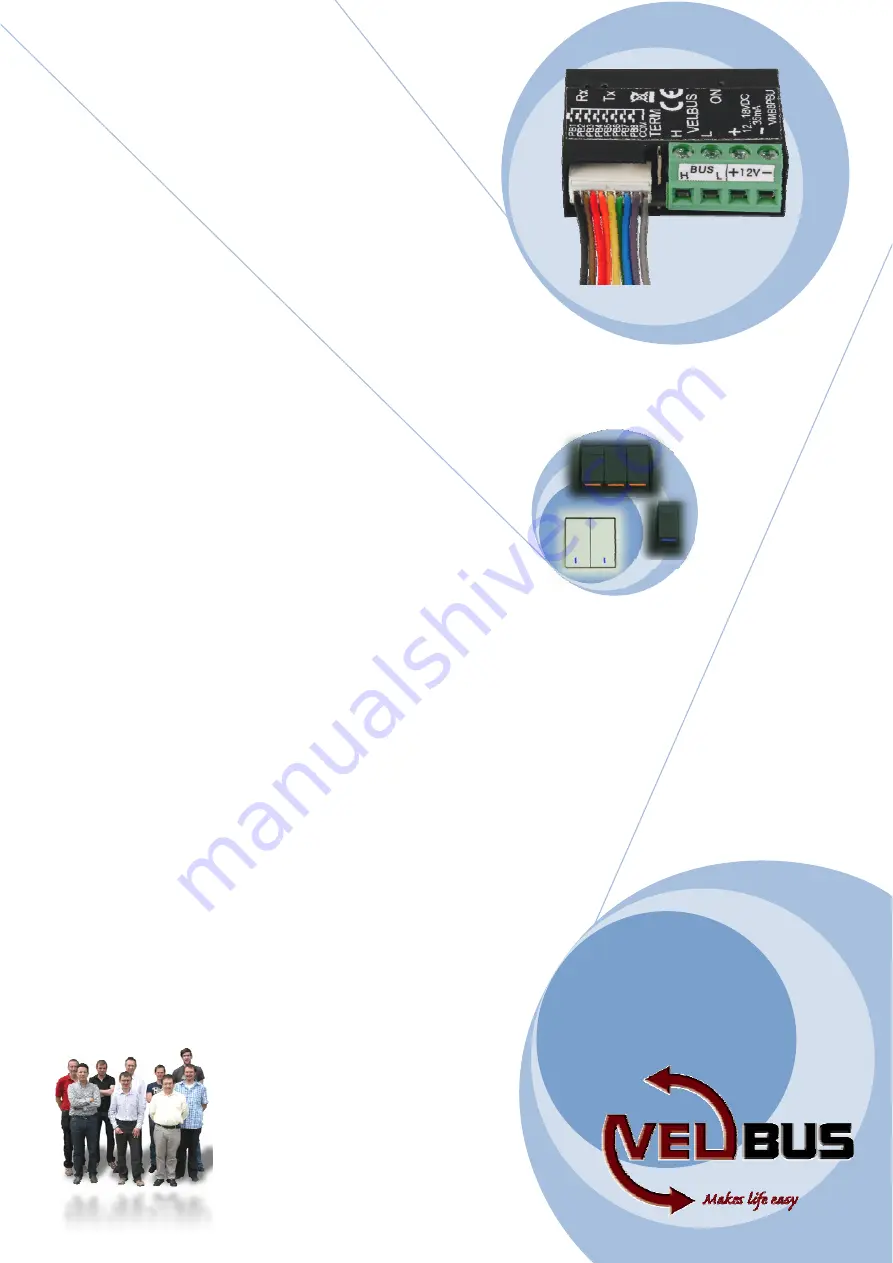
8-channel pushbutton 
module


V

V

V

M

M

M

B

B

B

8

8

8

P

P

P

B

B

B

U

U

U


Extended manual that explain how to use all possibilities of this 8-
channel pushbutton module and how you can connect up to 8 
pushbuttons from any brand to your Velbus installation.  


Velbus team 


Summary of Contents for VMB8PBU

Page 1: ...V V VM M MB B B8 8 8P P PB B BU U U Extended manual that explain how to use all possibilities of this 8 channel pushbutton module and how you can connect up to 8 pushbuttons from any brand to your Vel...

Page 2: ...10 USE 11 Address 11 Name 11 Response time 11 Suppressing 11 Inversion 11 Multichannel pushbutton 11 Double channel pushbutton 11 Suppressing 11 Lock Unlock 12 Backlighting 12 Feedback 12 Status feedb...

Page 3: ...tware Software addressing up to 250 addresses possible Pushbutton settings o Response time for each pushbutton adjustable between 0 1 2 or 3 seconds o Normally open or normally closed type o Double ch...

Page 4: ...Module type 8 channel pushbutton module including software version Pushbutton names Communication fault counter Memory content Time and date Turn off switch on or flashing of status LEDs The module c...

Page 5: ...VMB8PBU ed 1 8 channel pushbutton module 5 OVERVIEW 12345678C Velbus power supply Velbus Terminator Pushbutton connections Velbus Receiving LED Power LED Velbus LED...

Page 6: ...f modules more than 10 are connected on the Velbus cable or the Velbus cable is very long over 50m it is important to foresee a cable with sufficient wire diameter 0 5mm 2 of more Connect the bus and...

Page 7: ...the pushbutton The black connection wire PB of the LED is combined with one of the eight pushbutton connection wires The white connection wire C of the LED is combined with the common connection wire...

Page 8: ...8 8 channel pushbutton module VMB8PBU ed 1 Connecting NikoTM pushbuttons Tip Use ferrules on the wires for the pushbutton connections...

Page 9: ...of the eight pushbutton connection wires The white connection wire C of the LED is combined with the common connection wire COM for the pushbuttons Use ferrules to combine the connection wires Connect...

Page 10: ...from the distribution box In all other cases it must be removed Remark In a wiring scheme with a lot of branches a terminator is placed on a module inside the distribution box and on the control pane...

Page 11: ...are normally closed Multichannel pushbutton It is possible to control multiple channels via a single pushbutton With every press on the button the next channel will be selected Different actions can b...

Page 12: ...nscreen during wintertime the pushbuttons can be locked during this period Backlighting The indication LED on the pushbutton may glow softly to locate the pushbutton in the dark The brightness of the...

Page 13: ...a pushbutton Activating deactivating the switching program For each pushbutton the switching program can be activated or deactivated This can be done via the VelbusLink program or via pushbuttons tha...

Page 14: ...elated programs via a push on a Velbus pushbutton Deactivate wake up sleep time related programs via a push on a Velbus pushbutton Sunrise and sunset The switching program allows the use of the time o...

Page 15: ...el pushbutton module 15 VERIFY SOFTWARE VERSION The software version can be retrieved via the Velbuslink software Check the software version on http www velbus eu When a newer version is available dow...

Page 16: ...16 8 channel pushbutton module VMB8PBU ed 1 Velleman nv Legen Heirweg 33 9890 GAVERE 2011...

Reviews: