44
VEGAPULS 56K
Electrical connection
5 Electrical connection
5.1 Connection and connection
cable
Safety information
Ensure that the instrument is in currentless
condition. Always switch off the power supply
before you carry out terminal work on the radar
sensors. Protect yourself and the instrument,
especially when you use sensors which do not
work with low voltage.
Skilled staff
Instruments which are not operated with a
protective low voltage must only be connected
by skilled staff.
Connection
A standard two or four-wire cable (sensors with
separate supply) with max. 2,5 mm
2
can be
used for connection. Very often the "Electro-
magnetic pollution“ by electronic actuators,
energy lines and transmitting stations is so
considerable that the two or four-wire cable
should be screened.
We recommend to use a screening. This
screening prevents against future interferences.
Only earth the cable screens at two ends (on
the sensor and on the processing system) when
you have determined by a measurement that no
or only low earth compensating currents flow
via the screens. Use a very low impedance
earth connection (foundation, plate or mains
earth).
Ex-protection
If an instrument is used in hazardous areas, the
appropriate regulations, conformity certificates
and type approvals for systems in Ex-areas
must be noted (e.g. DIN␣ 0165).
Connection cable
Note that the connection cables must be speci-
fied for the expected operating conditions in your
systems. The cable must have an outer diam-
eter of 5␣ …␣ 9␣ mm (M20x1,5) or 3,5␣ …␣ 8,7␣ mm (
1
/
2
“␣ NPT). Otherwise the seal effect of the cable
entry will not be ensured.
Cables for intrinsically safe circuits must be
marked blue and must not be used for other
circuits.
Earth conductor terminal
On all VEGAPULS 56 sensors the earth con-
ductor terminal is galvanically connected to
the metal process connection.
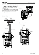
5.2 Connection of the sensor
After having mounted the sensor in the meas-
uring position acc. to the instructions in chap-
ter "4 Mounting and installation“, loosen the
closing screw on top of the sensor. The sensor
cover with the optional display can then be
opened. Unscrew the compression screw and
shift the screw over the approx. 10 cm
dismantled connection cable. The compres-
sion screw of the cable entry is protected with
a safety lock-in position against automatic
loosening.
Now loop the cable through the cable entry
into the sensor. Screw the compression screw
again to the cable entry and clamp the
dismantled wires of the cable to the appropri-
ate terminal positions.
The terminals operate without terminal screw.
Press the white opening buckets with a small
screwdriver and insert the copper core of the
connection line into the terminal opening.
Check the position of the lines in the terminal
position by slightly pulling on the connection
lines.

