9
4 Mounting instructions
B 61-300 • For supply and control cables
40488-EN-161114
OUT
IN
IP 20
1
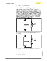
Fig. 4: Mounting on carrier rail
1 Fixing screw
2. Place the overvoltage arrester onto the rail and let it snap in
3. Tighten fixing screw
4.2 Mounting in housing
The overvoltage arrester is optionally available in a plastic or alu-
minium housing. Make sure when mounting that the cable glands
point downward. Thus avoids water ingress.
The carrier rail inside the housing is galvanically connected to the
ground terminal outside on the housing. For this function of the over-
voltage arrester, this ground terminal must be connected (low imped-
ance) with the potential equalization line (PA). The wire cross-section
must be at least 2.5 mm
2
, the cable must be as short as possible.
1
2
4
3
OU
T
IN
IP 20
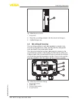
Fig. 5: Mounting in Aluminium housing
1 Overvoltage arrester
2 PE terminal
3 Pressure compensation
4 Ground terminal


