background image

5.8 Packet Capture

5.8.1 Packet Capture Setup

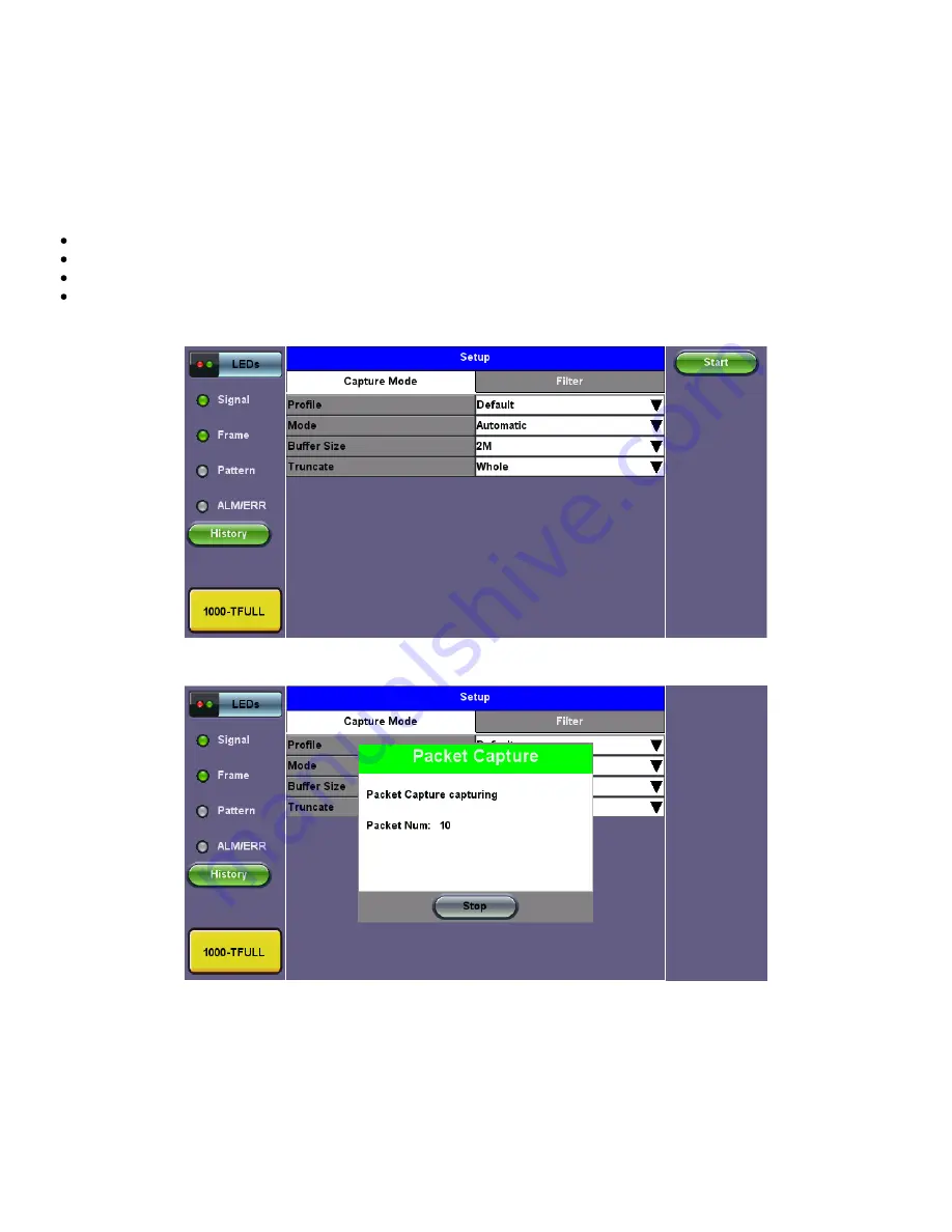
The packet capture function can be used to capture packets to Ethernet test ports. The packet capture format is compatible with

Wireshark and can be viewed on a PC.

Configure the following 

Capture Mode 

parameters:

Profile: 

Drop-down selections are Default, Delete, Save, Save As...

Mode: 

Automatic. Packet capture is automatically started when pressing the 

CAP ON 

function key.

Buffer Size: 

Defines the size of the storage allocated to packet capture.

Truncate: Captures the whole frame or first number of bytes of that frame.

Capture Mode Setup

Packet Capture In Progress

Packet Capture Save

RXT-6400_Module_Manual

Page 88 of 119

Summary of Contents for RXT-6400

Page 1: ......

Page 2: ... Selection 5 1 2 Port Setup 5 1 3 Measurement Settings 5 1 4 CDR Access 5 1 5 I2C Access 5 1 6 Pre emphasis 5 2 IP 5 2 1 IP Connection 5 2 1 1 Setup 5 2 1 2 Status 5 2 2 Trace Route 5 2 3 ARP Wiz 5 2 4 Ping 5 3 BERT 5 3 1 Setup 5 3 1 1 Header Settings 5 3 1 2 Traffic Settings 5 3 1 3 Error Injection 5 3 1 4 Starting Stopping a BERT 5 3 2 Results RXT 6400_Module_Manual Page 2 of 119 ...

Page 3: ...1 5 Starting Stopping a RFC 2544 Measurement 5 4 2 Results Standard Mode 5 4 3 Saving RFC 2544 Results 5 5 V SAM 5 5 1 V SAM Setup 5 5 1 1 Header Settings 5 5 1 2 Service Attributes 5 5 2 Results 5 6 Throughput Testing 5 6 1 Setup 5 6 1 1 General Throughput Settings Global Configuration 5 6 1 2 Per Stream Configurations 5 6 1 3 Traffic Settings Per Stream Configuration 5 6 1 4 Error Injection Sett...

Page 4: ... 5 8 Packet Capture 5 8 1 Packet Capture Setup 5 8 2 Packet Capture Results 6 0 Lane BERT 6 1 Lane BERT Set up 6 1 1 Lane BERT Results 6 1 2 Lane BERT Signal 6 1 3 Lane BERT Aggregate 6 1 4 Lane BERT Lane 6 1 5 Lane BERT Events 7 0 FEC 7 1 FEC Codeword Symbol Error Distribution 7 1 1 FEC Set Up 7 1 2 Results Summary 7 1 3 Alarms and Errors 7 1 4 Skew 8 0 PCS 8 1 PCS Set up 8 1 1 TX Lane Mapping an...

Page 5: ...s 8 3 Saving PCS Results 9 0 Advanced Optical Transceiver Test Stress Test 9 1 Transceiver Stress Test 9 2 Advanced Optical Transceiver Test 10 0 Warranty and Software 11 Certification and Declarations 12 0 About VeEX Go back to top RXT 6400_Module_Manual Page 5 of 119 ...

Page 6: ...rmission from VeEX Inc This device uses software either developed by VeEX Inc or licensed by VeEX Inc from third parties The software is confidential and proprietary of VeEX Inc The software is protected by copyright and contains trade secrets of VeEX Inc or VeEX s licensors The purchaser of this device agrees that it has received a license solely to use the software as embedded in the device and ...

Page 7: ...pable The platform must be turned off and unplugged from VAC mains when removing or inserting test modules For safety and EMC Electromagnetic Compatibility empty module slots must be properly covered with blank panel covers Prevent foreign objects from entering the TX300s before during and after module exchange or re configuration process They could create short circuits or damage internal fans Al...

Page 8: ...n battery packs or products containing relatively large Li ion battery packs Electrical Connectors Telephone lines may carry dangerous voltages Always connect the electrical test ports to known test interfaces which carry low level signals ESD Electrostatic Discharge Sensitive Equipment Test modules could be affected by electrostatic discharge To minimize the risk of damage when replacing or handl...

Page 9: ...t in class signal integrity no adapters required 400G Ethernet testing per IEEE 802 3bs specification with KP4 Forward Error Correction FEC Provides all the necessary features to test QSFP DD and OSFP transceivers networking equipment and 400GE links Advanced and flexible state of the art FPGA based design with native PAM4 transceivers provides future proof hardware support for 400GE evolution eme...

Page 10: ...XT 6400 Host Chassis refer to the RXT 1200 Platform Manual 4 2 Utilities Refer to the RXT 1200 Platform Manual for information about all Utilities and Tools available 4 3 Setup Accessing Setup Please see the RXT 1200 Platform Manual Getting Started section to launch Test Applications Go back to top Go back to TOC RXT 6400_Module_Manual Page 10 of 119 ...

Page 11: ...are releases please keep the test set software up to date Test Mode Selection RXT 6400 After selecting the test interface click OK The configuration parameters header bandwidth etc for each application on each of the ports are completely independent from one another All test feature combinations are allowed and completely independent Loopback BERT Throughput RFC2544 VSAM in dual port operation How...

Page 12: ... tests Once the operating mode and interfaces are selected independently configure the auto negotiation speed duplex and flow control settings for each port where applicable After configuring settings tap Apply to save changes Tap Discard to revert to previous selections Ethernet Home Menu 1GE Fiber Port Setup 1 GE Fiber Port Network Type LAN Flow Control Enable Disable Clock Source Internal Exter...

Page 13: ...LK GPS1PPS Clock Offset pmm 0 0 Link Fault Response Enable Disable 40 GE Setup 40 GE Port Network Type LAN Flow Control Enable Disable Clock Source Internal External 2Mbps 2MHz 1 5Mbps 1 5MHz 10MHz 1PPS RxFCf GPS1PPS Clock Offset ppm 0 0 Link Fault Response Enable Disable Go back to top Go back to TOC RXT 6400_Module_Manual Page 13 of 119 ...

Page 14: ...100 GE Setup Setup Clock Source Clock Offset RXT 6400_Module_Manual Page 14 of 119 ...

Page 15: ...Fault Response Disable Enable 400 GE Setup 400 GE Port 400G port profile Default Network Type LAN Flow Control Enable Disable Clock Source Internal External 2Mbps 2MHz 1 5Mbps 1 5MHz 10MHz 1PPS RxCLK GPS1PPS Clock Offset ppm 0 0 Link Fault Response Disable Enable Go back to top Go back to TOC 5 1 3 Measurement Settings 1GE 10GE 100 GE Measurement Setup RXT 6400_Module_Manual Page 15 of 119 ...

Page 16: ...The measurement and event log settings are configured in this screen Profile Last configuration Lock Delete Save Save as Default Mode Manual or timed Manual mode User starts and stops the measurements manually Timed mode User defines the duration of the test after the test is started the test will run for the configured duration and stop automatically TX Start Tx Rx or Tx Separate Configure how th...

Page 17: ... and RX CDR to be turned on Go back to top Go back to TOC 5 1 5 I2C Access I2CAccess Transceiver I2C MDIO Register Read Write Module information settings status and control Reconfigure the PHY and monitor status 5 1 6 Pre emphasis Pre emphasis RXT 6400_Module_Manual Page 17 of 119 ...

Page 18: ...orming the following Ethernet applications Ping Trace Route Web FTP ARPWiz VoIP IPTV testing and 1588v2 except Layer 2 Tap on IP from the Ethernet home menu to access Port and IP settings 5 2 1 1 Setup Select PPoE IPv4 or IPv6 from the Mode menu Point to Point Protocol over Ethernet PPoE Authentication PAP CHAP or CHAP PAP VLAN Off or 1 Tag ID VLAN ID Enter value 0 to 4095 Pri VLAN priority 0 to 7...

Page 19: ...ask DNS Off Manual or Auto If Manual is selected a DNS IP is required in order to use the URL as a destination Enter the IP address of the Domain Name System DNS Server providing domain name translation to IP addresses VLAN Off 1 Tag 2 Tags For each VLAN tag enter the following ID VLAN ID Enter value 0 to 4095 Pri VLAN priority 0 to 7 Go back to top Go back to TOC 5 2 1 2 Status Ensure the Status ...

Page 20: ... Address Resolution Protocol ARP to verify the status of each IP address in a user selectable IP range It is the standard method for finding a host s hardware address when only its network layer address is known Refer to ARP Wiz in the TX300S MTTplus RXT 1200 or UX400 platform manuals for more information on this feature including setup and results Go back to top Go back to TOC 5 2 4 Ping Ping is ...

Page 21: ...rame IP Address A default or user configured IP address is added to the frame Layer 4 Framed BERT same as Layer 1 2 3 Framed MAC Address A default or user configured Media Access Control MAC address is added to the frame IP Address A default or user configured IP address is added to the frame UDP Address A user defined source and destination port address is added to the frame BERT Setup Header Lay...

Page 22: ...e and Destination MAC address for Layer 2 Set the Source and Destination MAC and IP addresses for Layer 3 and Layer 4 VLAN Off 1 tag 2 tags 3 tags The user is able to configure up to 3 VLAN tags VLAN stacking for Q in Q applications VLAN stacking is an option MPLS Off 1 tag 2 tags 3 tags The user is able to configure up to 3 MPLS tags MPLS tag configuration is only available when the MPLS option i...

Page 23: ...OC VLAN Tab In the VLAN tab the following parameters are configured VLAN ID Configurable in the range 1 to 4094 VLAN ID is the identification of the VLAN which is basically used by the standard 802 1Q It has 12 bits which allows the identification of 4096 2 12 VLANs Of the 4096 possible VIDs a VID of 0 is used to identify priority frames and value 4095 FFF is reserved Maximum possible VLAN configu...

Page 24: ...oS Configurable in the range 0 to 6 This field is three bits in length and maps directly to IP Precedence TOS bits to provide Class of Service COS S bit Configurable 0 or 1 The S field is one bit in length and is used for stacking labels This is important as it is used to indicate the last label in the label stack TTL Configurable in the range 0 to 255 The default setting is 128 hops Used to decre...

Page 25: ...gnaling 100 Streaming Video 101 Voice 110 Routing 111 Reserve DSCP Differentiated Services Code Point The first six bits of the IP TOS can be edited to provide more granular service classification For more information on the definition of DSCP field in IPv4 and IPv6 headers refer to RFC 2472 Time To Live TTL Configurable in the range 0 to 255 Fragment offset byte Configurable in the range 0 to 65 ...

Page 26: ... of 1 bit time followed by a zero or light off for a duration of 1 bit time This pattern can be generated by the repeated transmission of the D21 5 code group Disparity rules are followed LFPAT Low Frequency Pattern The intent of this test pattern is to test low frequency RJ and also to test PLL tracking error This low frequency test pattern generates a one or light on for a duration of 5 bit time...

Page 27: ...r bit rates 2 23 1 8 388 607 bit pattern primarily intended for error and jitter measurements at bit rates of 34 368 and 139 264 kbps 2 15 1 32 767 bit pattern primarily intended for error and jitter measurements at bit rates of 1544 2048 6312 8448 32 064 and 44 736 kbps 2 11 1 2047 bit pattern primarily intended for error and jitter measurements on circuits operating at bit rates of 64 kbps and N...

Page 28: ...P Destination address IP Source address BERT Setup RX Filter selection UDP TCP Input Source Port and Destination Port BERT Setup RX Filter selection Go back to top Go back to TOC 5 3 1 2 Traffic Settings Traffic tab The user configures the traffic profile for the stream including traffic flow frame size frame type and transmit rate Traffic Flow Select from the following traffic flows Constant The ...

Page 29: ...t When traffic flow is equal to Burst two burst bandwidths are configured with burst time When traffic flow is equal to Ramp starting and an ending bandwidth are configured along with the bandwidth step size and duration BERT Setup Constant Traffic Frame Size Limitations Layer 1 framed mode Frame size configuration is not available Layer 1 unframed mode Traffic profile is constant at 100 bandwidth...

Page 30: ...ser can start the test The selected tests will run automatically When all the tests are complete the test will stop automatically If the BERT test suite needs to be stopped before they are done then simply press the Stop button located in the actions drop down menu The status of each selected test can be seen in the Results tab Far End Unit Controlled with Loop Up Down Commands If the far end unit...

Page 31: ...rface then the utilization value is 10 or 100Mbps of the total link capacity or Line Rate Number of bytes Pause Frames Total number of transmitted and received Ethernet pause flow control frames BERT Results Summary Go back to top Go back to TOC 5 3 2 2 Errors Errors tab The following errors Current and Total are displayed Bits Indicates errors related to test pattern Bit Error or LSS Pattern Loss...

Page 32: ... Events Go back to top Go back to TOC 5 3 2 4 Traffic Traffic tab The following Traffic statistics are displayed Frame type Test and non test frames Traffic type Layer 2 and Layer 3 Unicast Broadcast and Multicast frame percentage Frame size distribution Pause frames Tap on the graph for detailed screens BERT Results Traffic Distribution RXT 6400_Module_Manual Page 32 of 119 ...

Page 33: ...hernet pause flow control frames BERT Results Frames Go back to top Go back to TOC Traffic Type tab The following Traffic distribution statistics are displayed in Count and Percentage Layer 2 Unicast frames Number of Unicast frames received without FCS errors Layer 2 Broadcast frames Number of Broadcast frames received without FCS errors Broadcast frames have a MAC address equal to FF FF FF FF FF ...

Page 34: ...me Size Go back to top Go back to TOC 5 3 2 5 Rates Rates tab Rate statistics are displayed in a graph format Tap on either gauge to see rate details in table form The table shows transmitted Tx and received Rx current minimum maximum and average frame rates FPS and Data Rates Mbps Frame rate in Frames per second FPS Number of received frames including bad frames Broadcast frames and Multicast fra...

Page 35: ... 5 3 2 7 Alarms Alarms tab The following Alarms Current and Total are displayed LOS Loss of Signal LOS Sync Loss synchronization Pattern Loss Indicates errors related to test pattern Service disruption associated with loss of signal Current Duration of the current service disruption Total Total accumulated duration of the service disruptions Min Max Minimum and maximum duration of the service disr...

Page 36: ... signals Loss of Signal LOS and the Saturation levels for optical signals are shown graphically including the level measurement in dBm BERT Results Signal Signal Page 2 Page 2 displays the Optical module transceivers information which includes Vendor name Part Number and Optical Wavelength Tap on the Decode button to view additional information on SFP optics BERT Results Signal Page 2 RXT 6400_Mod...

Page 37: ...signal Offset Indicates the difference between the standard rate and the rate of the input signal Min ppm Indicates the difference between the standard rate and the minimum deviation detected in the input signal Max ppm Indicates the difference between the standard rate and the maximum deviation detected in the input signal Go back to top Go back to TOC RXT 6400_Module_Manual Page 37 of 119 ...

Page 38: ...44 test suite consists of and performs a set of four automated tests throughput latency frame loss and burst or back to back to qualify the performance of a network link under test The tests are especially popular for the verification of network links with certain service level agreements SLA The following settings must be configured prior to RFC 2544 testing Test layer Layer 2 3 4 Frame header PB...

Page 39: ...nature field and other proprietary data RX Filter Tab VLAN Tab MPLS Tab IP Tab RFC 2544 Data tab Go back to top Go back to TOC 5 4 1 2 Frame Settings Frames tab User configures the following Preset Frames User selects from a list of recommended test frame sizes defined in RFC 2544 Test frames are 64 128 256 512 1024 1280 and 1518 bytes The default selected frames are 64 and 1518 bytes To select de...

Page 40: ...e configured for all of the test frames selected in the frame settings tab A Pass Fail criteria will be applied when the threshold settings are enabled Select a rate type from the drop down menu that will be used to determine pass fail criteria Options are of Max Rate of Line Rate Utlized Line Rate Mbps For example if the throughput threshold value for a 64 byte frame is configured for 80 then a P...

Page 41: ...ne rate or in Mbps For example if the user configures the Max Rate to be 90 and the negotiated line rate of the link is 100Mbps then the maximum transmit rate will be 90Mbps or 90 of the line rate Resolution Input any value between 0 001 and 1 The default value is 1 Resolution refers to the resolution in searching for the throughput rate If 1 is selected the throughput rate will be searched with 1...

Page 42: ...ed Enter up to 100 of the negotiated line rate or enter the rate in Mbps Duration 5 to 999 seconds The default value is 20 seconds This is the amount of time that the latency test will be performed for each test frame size Repetitions 1 to 100 The default value is 1 This is the amount of times that the latency test will be repeated for each test frame size RFC 2544 Setup Latency Settings Go back t...

Page 43: ...Go back to top Go back to TOC Burst Back to Back tab Max Rate Up to 100 of the negotiated line rate The default value is 1000 ULR Mbps In the burst test frames are always transmitted at the maximum rate for a given minimum and maximum burst duration The user may configure this rate as a of the total line rate or in Mbps For example if the user configures the Max Rate to be 90 and the negotiated li...

Page 44: ...nd from the control unit before the RFC 2544 test suite can be started To loop up the far end unit with the manual mode loop up down commands configure the control settings mode to manual Enter the MAC and or IP address of the far end unit Send the loop up command by pressing Loop Up Once the far end unit has been looped back start the test by pressing the Start button When the all of the selected...

Page 45: ...verhead Line Rate Utilization of Line Rate For example if we transmit 100Mbps on a 1Gbps interface then the utilization value is 10 or 100Mbps of the total link capacity or Line Rate Total Frames Bad Frames Pause Frames Total number of transmitted and received Ethernet pause flow control frames RFC 2544 Results Summary Go back to top Go back to TOC Signal tab The Signal tab fiber ports only displa...

Page 46: ...graphical and table formats Use the drop down menu to change the display format Graphical Throughput results are displayed in a bar graph form Summary table and test log table display byte size Tx Percentage of test frames transmitted by the unit Rx Percentage of test frames received by the unit Thresholds Pass Fail test status determined by test criteria set in the Threshold tab RFC 2544 Results ...

Page 47: ...rame jitter measurements results are displayed in the following formats Use the drop down menu to select the Latency format Graphical Latency results displayed in line graph form Latency us vs Frame size bytes Summary and Test log tables display byte size Latency us Round trip delay latency RXT 6400_Module_Manual Page 47 of 119 ...

Page 48: ...d Data rate used for latency test Pass Fail test status RFC 2544 Results Latency Summary RFC 2544 Results Latency Graphical RFC 2544 Results Latency Test Log RFC 2544 Results Latency Jitter Graphical RXT 6400_Module_Manual Page 48 of 119 ...

Page 49: ...age of frames not received Use the drop down menu to select the Frame Loss format Summary and Test log tables display test frame length byte size frame loss from received traffic and rate transmitted Graphical Frame Loss displayed in line graph form Frame size bytes vs Rate Tap on the magnifying glass to see the legend RXT 6400_Module_Manual Page 49 of 119 ...

Page 50: ...rstability back back results are the number of frames successfully transmitted received at the line rate It is displayed in the following formats Summary table Displays Average Frame Count received for each test frame length Test log table Displays Average Frame Count and Duration seconds for each test frame length RXT 6400_Module_Manual Page 50 of 119 ...

Page 51: ...RFC 2544 Results Burstability Summary RFC 2544 Results Burstability Test Log FEC tab RFC 2544 Results FEC Summary RFC 2544 Results FEC Alarms Errors RXT 6400_Module_Manual Page 51 of 119 ...

Page 52: ...Errors Lane Details RFC 2544 Results FEC Alarms Errors Corr Symbol Details The FEC Correctable Symbol Breakdown page shows the Symbol Errors per FEC Codeword distribution which is important to RXT 6400_Module_Manual Page 52 of 119 ...

Page 53: ...ayload Ethernet traffic hence not counted on this screen RFC 2544 Results FEC Skew Go back to top Go back to TOC 5 4 3 Saving RFC 2544 Results Once the test has been stopped the results can be saved by pressing the Save key on the VePAL s keypad The results will be saved and named automatically Once the results are saved the user may view or rename the results file by going to Utilities Files Save...

Page 54: ...ingle 10 100 1000 or 10G Ethernet line at a bandwidth ranging from 0 to the line rate allowing for more realistic stream testing The Frame Delay Variation also known as packet jitter was not included in RFC 2544 Jitter is a critical parameter for real time voice and video services It is now part of the SAM test suite RFC 2544 validates the service parameters like frame loss throughput and latency ...

Page 55: ...short period of time the EIR test passes if the received traffic rate is between the CIR minus the margin allowed by the FLR and CIR EIR Step 3 Traffic Policing Overshoot Test The purpose of the Traffic Policing Test is to ensure that when transmitting at a rate higher than the allowed CIR EIR the excess traffic will be appropriately blocked to avoid interference with other services For this test ...

Page 56: ...on and Performance Tests can be enabled independently CIR Test Config Tap on the box to configure the Committed Information Rate Test on another screen Duration Select the Service Performance Test duration Options are 15min 30min 1hr 2hr 24hr or user defined If user defined is selected input a duration between 1 10000 min Enabling Disabling Tests A check next to the Service number in the Service S...

Page 57: ...Settings Service Select a service to configure Service Name Assign a name to the service if desired Frame Size Type Fixed or EMIX 1GE only A fixed frame size is chosen as default Frame Size For Fixed Traffic Flow Input a fixed frame size within the range of 64 10000 bytes by tapping the value box For EMIX 1GE only The default value is abceg Tap the zoom magnifying glass icon to define other values...

Page 58: ...bone MAC Source Backbone MAC Destination Ethernet Type I SID VLAN ID Priority Type MPLS TP MPLS TP MAC Source MPLS TP MAC Destination Ethernet Type VLAN ID Priority Type LSP PW CW After making changes tap Apply to All for MPLS TP configuration Please see RFC 2544 Setup and follow the setup procedure to configure the remaining Header Settings for V SAM V SAM Setup Services Header Settings V SAM Set...

Page 59: ...hernet frame rate starting at the MAC address field and ending at the CRC Utilized Line Rate ULR Measures the average Ethernet frame rate starting with the overhead and ending at the CRC V SAM Services Header Excess Information Rate EIR Maximum rate above the CIR at which the customer can send frames that will be forwarded on a best effort basis but may be dropped in the event of congestion within...

Page 60: ...ic conforming to the CIR Enter a percentage from 0 100 FTD Maximum transfer time that the frames can take to travel from source to destination and still be compliant with the SLA FTD is only guaranteed for traffic conforming to the CIR Values are measured in us ms or sec Input a value within the digital range of 001 999 and 1 us 999sec The user can also choose to Disable the FTD threshold evaluati...

Page 61: ...fig Tests tab lists the Pass Fail status of each service and test Tapping on the table brings up a screen with CIR CIR EIR and Policing Test results for the chosen Service CIR CIR EIR Test and Policing tabs display min mean and max values for IR Mbps FTD FDV Frame Loss Count and Frame Loss Ratio If Step Load was selected for the CIR Test these values will be displayed for each step If any measured...

Page 62: ...otal transmitted frames CIR Test Service 1 CIR test The test passes if all measured values are below the thresholds configured If a threshold is disabled it will not be evaluated towards pass fail criteria CIR EIR Test Service 1 CIR EIR test The test passes if the received IR value is between the CIR minus the margin allowed by the FLR and CIR EIR Policing Test Service 1 RXT 6400_Module_Manual Pag...

Page 63: ...n allowed by the FLR but does not exceed the allowed CIR EIR Results Config Tests Summary Summary The Summary tab displays the status of each service and test as Pass Failed Pending or Disabled Perf Test Service 1 Go back to top Go back to TOC Performance Test RXT 6400_Module_Manual Page 63 of 119 ...

Page 64: ...of the frames are errored or missing in a one second interval Availability is only guaranteed for traffic conforming to the CIR Total RX Frames Total number of frames received Errored Frame Count Number of frames with CRC or IP Checksum errors Measured values that do not meet the service test parameters set in the Bandwidth and Threshold tabs cause the test to fail The Summary tab displays the sta...

Page 65: ...as a global or aggregate measurement This application is very useful in verifying the transport of traffic with different prioritization settings across a network link The test helps verify that the network can handle high priority traffic and low priority traffic accordingly Go back to top Go back to TOC 5 6 1 Setup Unless otherwise noted the Frame Header and related setups are the same as the on...

Page 66: ... event is logged with corresponding time stamp SDT Measurement Enable Disable The Service Disruption Test is triggered based on user established thresholds SDT Measurement Trigger us Any inter frame gap that is equivalent or greater than the configured threshold will trigger the SDT measurement This is useful if a known threshold is expected from a given network under test For example if the known...

Page 67: ...ches the number of times entered in the flood range For information on header configuration please see BERT Header Settings in the BERT section Throughput Setup Header Settings per Stream Multiple Streams MAC IP Address Setup If all of the streams are going to the same far end unit then the MAC IP destination addresses must be the same on all of the streams If any of the traffic streams are going ...

Page 68: ...n Error injection can be performed during test The type of errors and error injection are configured in the Error Injection tab Once the test is running error injection can be performed by pressing the Error Inject button on the right side of the screen Stream Select the stream to configure Error type Select from CRC IP Checksum Layer 3 4 only TCP UDP Checksum Layer 4 only Sync Header Error Block ...

Page 69: ...pe Local Fault Remote Fault PCS HI BER PCS LOBL Alarm Flow The alarm flow determines how the selected alarms will be injected A specific Count or Continue continuous can be selected Alarm Length 1s 10s or 100s Throughput Alarm Injection Setup Go back to top Go back to TOC 5 6 1 6 Summary The summary screen lists the source destination and VLAN information of each stream Tap on the appropriate box ...

Page 70: ...Throughput Test Summary VLAN List Throughput Test Summary Port List Throughput Test Summary MPLS List RXT 6400_Module_Manual Page 70 of 119 ...

Page 71: ...5 6 1 7 FEC Throughput Test FEC Summary Throughput Test FEC Alarm Errors Throughput Test FEC Alarm Errors Lane Details RXT 6400_Module_Manual Page 71 of 119 ...

Page 72: ...Throughput Test FEC Alarm Errors Corr Symbol Details Throughput Test Skew Go back to top Go back to TOC RXT 6400_Module_Manual Page 72 of 119 ...

Page 73: ...st receive a loop up command from the control unit before the Throughput test suite can be started To loop up the far end unit with the manual mode loop up down commands configure the control settings mode to manual Enter the MAC and or IP address of the far end unit Send the loop up command by tapping on the Loop Control button and pressing Loop Up Once the far end unit has been looped back start...

Page 74: ...ves from Y 1541 U denotes unspecified or unbounded and signifies that no objective was established for this parameter and default Y 1541 objectives do not apply Parameters designated with U are occasionally inconsistent and poor IP Network QoS Class Definitions and Network Performance Objectives Classes 0 3 IP Network QoS Class Definitions and Network Performance Objectives Classes 4 7 RXT 6400_Mo...

Page 75: ...rface then the utilization value is 10 or 100Mbps of the total link capacity or Line Rate Framed Rate Payload MAC IP Header VLAN Tag Type Length CRC Payload Total Overhead Line Rate in Mbps Data Rate Payload Payload Total Overhead Line Rate Total of frames bad frames and pause frames Throughput Results Global Aggregate Go back to top Go back to TOC The Global Signal screen fiber ports only display...

Page 76: ...difference between the standard rate and the minimum deviation detected in the input signal Max ppm Indicates the difference between the standard rate and the maximum deviation detected in the input signal Go back to top Go back to TOC The Global Errors screen displays the Current and Total error count of all streams Sync Header Error Block Type Error FCS CRC Number of received frames with an inva...

Page 77: ...tal accumulated duration of the service disruptions Min Max Minimum and maximum duration of the service disruption events No of Occurrences Counter of service disruption events Local Remote Fault PCS HI BER PCS High BER PCS LOBL PCS Loss of Block Lock Throughput Results Global Alarms Go back to top Go back to TOC The Global Events screen displays the Time Event Type Number of Events and Test Type ...

Page 78: ...tics Frames tab The following Frame distribution statistics are displayed in Count and Percentage Received RX frames Total frames Test frames VLAN tagged frames Q in Q VLAN stacked frames Non test frames Transmitted TX frames Total frame Total frames transmitted Pause frames Total number of transmitted and received Ethernet pause flow control frames Throughput Results Frames Type RXT 6400_Module_M...

Page 79: ...mes Go back to top Go back to TOC 5 6 2 3 Per Stream Results The Per Stream tab displays the same type of statistics as seen in Global Results but for each stream For descriptions of the parameters in each tab with the exception of Rates please refer back to Global Aggregate Results Summary Framed rate data rate of bytes total of frames associated with each stream Errors Errors associated with eac...

Page 80: ...frames with an invalid Frame Check Sequence FCS IP Checksum Invalid IP Frame Check sequence TCP UDP Checksum Layer 4 only Jabber frames Number of received frames larger than 1518 bytes containing an invalid FCS Runt frames Number of received frames smaller than 64 bytes containing an invalid FCS Frame Loss Frame Loss OOS Throughput Results Errors per Stream Throughput Results Errors per Stream pag...

Page 81: ...ing the test No of Occurrences Number of service disruption events SDTs No of SDT Violations Number of instances the SDT threshold was met or exceeded SDT Per Stream Results Go back to top Go back to TOC The Per Stream Events screen displays a Date and Time stamped record of bit errors alarms and other anomalies pertaining to each stream Throughput Results Events per Stream RXT 6400_Module_Manual ...

Page 82: ...aining to each stream Throughput Results Traffic per Stream The Per Stream Delay screen displays the frame delay information pertaining to each stream The Histogram shows the sampling points for the delay Round Trip Delay Results and Histogram Throughput Results Delay per Stream RXT 6400_Module_Manual Page 82 of 119 ...

Page 83: ...gram One Way Delay Results and Histogram Table and Graph Throughput Results Delay per Stream One Way Delay Throughput Results One Way Delay Histogram Graph Throughput Results One Way Delay Histogram Table RXT 6400_Module_Manual Page 83 of 119 ...

Page 84: ... see rate details Throughput Results Rates per Stream Throughput Results Rates per Stream Rate Details Go back to top Go back to TOC 5 6 2 4 Saving Throughput Multiple Streams Results Once the test has been stopped the results can be saved by pressing the Save key on the VePAL s keypad The results will be RXT 6400_Module_Manual Page 84 of 119 ...

Page 85: ...ename the results file by going to Utilities Files Saved For more information on retrieving saved test results refer to File Management in the TX300S MTTplus RXT 1200 or UX400 platform manuals for more information Go back to top Go back to TOC RXT 6400_Module_Manual Page 85 of 119 ...

Page 86: ...or days Tap on View Setup to view test setup parameters Setup cannot be configured from this menu Tap on the green Start button to begin Autoscripting The soft LED light indicates the status of finished tests Green No error or alarm was detected Red An error or alarm was detected Starting the test brings up the BERT Throughput Results tab Test status is displayed in green on the bottom of the scre...

Page 87: ...File Manager Saved Results Go back to top Go back to TOC RXT 6400_Module_Manual Page 87 of 119 ...

Page 88: ...ing Capture Mode parameters Profile Drop down selections are Default Delete Save Save As Mode Automatic Packet capture is automatically started when pressing the CAP ON function key Buffer Size Defines the size of the storage allocated to packet capture Truncate Captures the whole frame or first number of bytes of that frame Capture Mode Setup Packet Capture In Progress Packet Capture Save RXT 640...

Page 89: ...re results press Stop To save result packets and view results tap YES when asked to view results Results are saved in PCAP format and are automatically named Wire shark will launch afterwards and display the results The file is stored in the Files folder It can be viewed on the test set or exported and analyzed on PC Wireshark Refer to File Management in the TX300S MTTplus RXT 1200 or UX400 platfo...

Page 90: ...Destination Protocol Length Info Middle and Lower Sections Frame details Ethernet frame details Go back to top Go back to TOC RXT 6400_Module_Manual Page 90 of 119 ...

Page 91: ...Setup In newer test sets the unit will be able to toggle between single frequency or per lane frequency measurements Lane BERT Setup Per Lane 1 Select the test rate and test pattern The same test pattern can be configured for all lanes or a different test pattern can be configured per lane 2 Press TX Start then press Start The options to set PRBS patterns per lane or for all lanes is available in ...

Page 92: ...2 The Signal tab fiber ports only displays the receiving RX and transmitting TX optical level measured by the QSFP28 QSFP DD QSFP or OSFP transceiver Loss of Signal LOS and the Saturation level for the optical signals are shown graphically including the level measurement in dBm for each lane Signal Page 1 Signal Page 2 Signal Page 3 RXT 6400_Module_Manual Page 92 of 119 ...

Page 93: ...e rate of the input signal Min ppm Indicates the difference between the standard rate and the minimum deviation detected in the input signal Max ppm Indicates the difference between the standard rate and the maximum deviation detected in the input signal Signal Page 3 Signal Page 4 5 Page 4 5 displays the Optical module information and status Signal Page 4 Signal Page 5 RXT 6400_Module_Manual Page...

Page 94: ...gate tab displays errors related to the test pattern Bit Error or Pattern Loss Aggregate Go back to top Go back to TOC 6 1 4 Lane The Lane tab displays Pattern Loss and Bit Errors for each lane PCS Results Alarms Errors RXT 6400_Module_Manual Page 94 of 119 ...

Page 95: ... back to TOC 6 1 5 Events A time stamped record or log of anomalies alarms test status start stop and test application are displayed PCS Results Events Go back to top Go back to TOC RXT 6400_Module_Manual Page 95 of 119 ...

Page 96: ...table Errors Identify how hard FEC is working Benchmark Compare transceiver preformances Beyond 15 Symbol Errors per Codeword the errors become Uncorrectable and start affecting the payload Zero post FEC Errors Client Test traffic payload must remain Error Free no uncorrectable errors Go back to top Go back to TOC 7 1 1 FEC Set Up Stress Test Setup After configuring setup tap Start FEC Setup RXT 6...

Page 97: ...TOC 7 1 2 FEC Results Summary Results Summary Tap on the Results Summary tab to view test results FEC Results Summary Go back to top Go back to TOC 7 1 3 Alarms and Errors FEC Alarms Errors RXT 6400_Module_Manual Page 97 of 119 ...

Page 98: ...FEC Results Alarms Errors Lane Details FEC Results Alarms Errors Corr Symbol Details RXT 6400_Module_Manual Page 98 of 119 ...

Page 99: ...Go back to top Go back to TOC 7 1 4 Skew FEC Skew Go back to top Go back to TOC RXT 6400_Module_Manual Page 99 of 119 ...

Page 100: ...ane Stresses the de skew function on the receiver side Skew alarm threshold value User configurable threshold for Skew alarm PCS Set Up TX Lane Mapping and Skew 8 1 2 Tx Alarm Error Injection Error Injection per PCS lane Invalid Sync header first 2 bits of the 64 66 block header Invalid alignment marker inserted every 16383 block on each virtual lane it contains the Virtual lane identifier BIP gen...

Page 101: ...Go back to top Go back to TOC 8 2 Results 8 2 1 Summary PCS Results Summary Go back to top Go back to TOC 8 2 2 RX Lane Skew PCS RX Lane Skew RXT 6400_Module_Manual Page 101 of 119 ...

Page 102: ...Go back to top Go back to TOC 8 2 3 Alarms and Errors PCS Results Alarms and Errors Go back to top Go back to TOC 8 2 4 Events PCS Results Events RXT 6400_Module_Manual Page 102 of 119 ...

Page 103: ... A window will open giving the option of naming the results file Enter the desired name for the file and tap apply The results will be saved PCS Results Save Once the results are saved they can be viewed or renamed by going to Tools System Settings screen Files Go back to top Go back to TOC RXT 6400_Module_Manual Page 103 of 119 ...

Page 104: ...ng optical signal power levels Lane BERT pre FEC performance voltage and frequency swing tolerances I2C MDIO registers read write pre emphasis manipulation all the way to verifying error free Ethernet Throughput 9 1 Transceiver Stress Test Stress Test Setup After configuring setup tap Start Stress Test Setup Stress Test Summary Tap on the Summary tab to view the test summary Stress Test Summary RX...

Page 105: ... RX Stress Test Signal Page 1 Stress Test Signal Tab Page 2 Tap on the Signal tab to view Signal Level TX Stress Test Signal Page 2 Stress Test Signal Tab Page 3 Tap on the Signal tab to view Signal Frequency Stress Test Signal Page 3 RXT 6400_Module_Manual Page 105 of 119 ...

Page 106: ...on the Signal tab to view QSFP Optical Module Information Stress Test Signal Page 4 Stress Test Signal Tab Page 5 Tap on the Signal tab to view QSFP Optical Module Status Stress Test Signal Page 5 RXT 6400_Module_Manual Page 106 of 119 ...

Page 107: ...ERT tab and tap Start The test will show as running Stress Test Pre FEC BERT Aggregate Pre FEC BERT Aggregate Pass Once the test has finished the screen will show as Pass Stress Test Pre FEC BERT Aggregate PASS RXT 6400_Module_Manual Page 107 of 119 ...

Page 108: ... BERT Lane tab and tap Start The test will show as running Stress Test Pre FEC BERT Lane Pre FEC BERT Lane Pass Once the test has finished the screen will show as Pass Stress Test Pre FEC BERT Lane Pass RXT 6400_Module_Manual Page 108 of 119 ...

Page 109: ... Pre FEC BERT Frequency Offset Pre emphasys settings and I2C registers read write access Use the check boxes to enable or disable the different sub tests Results The right side of the screen shows the different results The status indicators on top Pre BER Frequency Offset Temperature TX Optical Power RX Optical Power Supply Voltage not only show the current results but provide access to the detail...

Page 110: ...ansceiver Module Histogram Tab Tap on the histogram tab can be viewed in Table or Graph form Advanced Optical Transceiver Histogram Graph Advanced Optical Transceiver Histogram Table RXT 6400_Module_Manual Page 110 of 119 ...

Page 111: ...Voltage Tab Advanced Optical Transceiver Voltage Pre FEC BERT Tab Advanced Optical Transceiver Pre FEC BERT RXT 6400_Module_Manual Page 111 of 119 ...

Page 112: ...ceiver Freq Offset Pre Emphasis Tab Tap on the Pre Emphasis tab to view the TX Pre equalization settings To return to the previous screen tap on the red cross Advanced Optical Transceiver Pre Emphasis RXT 6400_Module_Manual Page 112 of 119 ...

Page 113: ... Tap on the I2C tab to view the I2C Access To return to the previous screen tap on the red cross Advanced Optical Transceiver I2C Read Write Go back to top Go back to TOC RXT 6400_Module_Manual Page 113 of 119 ...

Page 114: ...ct instructions In the event that VeEX receives notice during the Warranty Period that any Hardware does not conform to this Limited Warranty Customer s sole and exclusive remedy and VeEX s sole and exclusive liability shall be for VeEX at its sole option to 1 repair the Hardware at no charge using new or refurbished replacement parts in accordance with VeEX s Return Policy 2 exchange the Hardware...

Page 115: ... Software in an environment other than that intended or recommended by VeEX in the applicable Documentation b modifications to the Software not made or authorized by VeEX c third party hardware or software provided by any third party and not authorized by VeEX for use with the Software d used other than in its most current version to the extent that any failure of the Software would have been avoi...

Page 116: ...S RESELLERS DISTRIBUTORS OR LICENSORS HAVE BEEN ADVISED OF THE POSSIBILITY OF SUCH DAMAGES IN NO EVENT SHALL THE CUMULATIVE LIABILITY OF VEEX ITS DIRECTORS OFFICERS EMPLOYEES AFFILIATES SUPPLIERS MANUFACTURERS RESELLERS DISTRIBUTORS OR LICENSORS TO CUSTOMER WHETHER IN CONTRACT TORT INCLUDING WITHOUT LIMITATION NEGLIGENCE STRICT LIABILITY OR OTHERWISE EXCEED THE AMOUNTS ACTUALLY PAID TO VEEX BY CUS...

Page 117: ...EE Position Statement The Council of the European Union and the European Parliament adopted Directive 2002 95 EC January 27 2003 to Reduce the use of certain Hazardous Substances RoHS in Electrical and Electronic Equipment and Directive 2002 96 EC on Waste Electrical and Electronics Equipment WEEE with the purpose of reducing the environmental impact of waste electrical and electronic equipment Bo...

Page 118: ...Go back to top Go back to TOC RXT 6400_Module_Manual Page 118 of 119 ...

Page 119: ... a worldwide distribution channel provides uncompromised product support Visit us Online at www veexinc com for latest updates and additional documentation VeEX Incorporated 2827 Lakeview Court Fremont CA 94538 USA Tel 1 510 651 0500 Fax 1 510 651 0505 Customer Care Tel 1 510 651 0500 Email customercare veexinc com Go back to top Go back to TOC RXT 6400_Module_Manual Page 119 of 119 ...

Reviews: