background image

35

© VeEX Inc. All Rights Reserved.

Ethernet

MX Discover Remote Partner

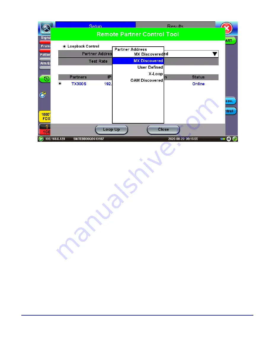
Loop Control

The

Loop Control

button becomes available on the right side menu when any Ethernet application (V-SAM,

RFC 2544, Throughput, BERT) is selected. Press the

Loop Control

button to configure loop up and loop down

commands necessary to control a far-end unit. The loop up command contains information about the test layer.
Looping back test traffic is possible as follows:

l

MX Discovered:

Lists MX discovered devices. Select from the list of discovered devices to loop up/-

down

l

User Defined:

Input the destination IP address of the far-end device

l

X-Loop:

Loops non-VeEX networking equipment.

Summary of Contents for MTX150 Series

Page 1: ...MTX150x User Manual Multi Service Installation Maintenance Test Set P N D07 00 148P Rev B00 ...

Page 2: ...tted electronically without prior agreement and written consent of VeEX Incorporated as governed by International copyright laws Information contained in this manual is provided as is and is subject to change without notice Trademarks of VeEX Incorporated have been identified where applicable however the absence of such identification does not affect the legal status of any trademark Copyright 202...

Page 3: ...nnectors 16 Safe Module Handling 16 Electrical Connectors 16 ESD Electrostatic Discharge Sensitive Equipment 16 Introduction 18 Product Specifications 18 Basic Operation 19 MTX150X Chassis Overview 19 MTX150X Connector Panel 19 Hard Buttons and Interfaces 21 Special Functions 23 Touch Screen Display 24 Platform Screen Icons 25 LEDs 25 Home Menu and Screen Icons 27 Mode Port Selection 27 Ethernet 2...

Page 4: ...IPv4 or IPV6 38 Status 39 Trace Route 39 Trace Route Setup 40 Results 41 ARP Wiz 41 ARP Setup 41 ARP Result 42 Ping 42 Ping Testing 42 Ping Setup 43 Ping Results 43 BERT 44 BERT Setup 44 Overview 45 Header Settings 46 Traffic 56 Error Injection 59 Starting Stopping a BERT 60 BERT Results 61 Summary 61 Errors 62 Events 63 Traffic Settings 63 4 VeEX Inc All Rights Reserved Table of Contents ...

Page 5: ... Background Results Advanced SLA Mode 93 Peer to Peer and Asymmetric Testing 94 Asymmetric Testing Setup 95 Unit as Controller Setup Process 95 Unit as Responder Setup Process 97 RFC 2544 Local and Remote Test Setup 98 Test Results 99 Viewing and Managing Files 100 Enabling To USB and From USB Functions 101 Downloading Files To USB 101 V SAM 101 Test Methodology 102 Phase 1 Service Configuration T...

Page 6: ...ughput Multiple Streams Test Results 137 Global Aggregate Results 137 Per Stream Results 144 Saving Throughput Multiple Streams Results 149 Viewing and Managing Files 150 Enabling To USB and From USB Functions 151 Downloading Files To USB 151 Layer 4 Applications 152 TCP Protocol and Overview 152 Layer 4 Applications Configuration 157 V Perf 158 Server Client Unidirectional Configuration and Resul...

Page 7: ...Wander Analysis PC Software 181 TIE Measurement Results 182 MTIE TDEV Analysis 182 MTIE TDEV Analysis Report in PDF 183 ESMC SSM 184 Setup 187 Results 187 Monitor 188 Capture 188 Phy Mode 189 Net Wiz 190 Cable Test 191 Discovery Setup 192 Discovery Results 192 Autoscripting 194 Setup 195 Results 195 L2 Control Protocol Transparency Test L2CP 196 Setup 196 Fiber Channel 202 Fiber Channel Applicatio...

Page 8: ... Channel layers and functionality 222 Setup 223 Traffic Generation and Error Injection 223 Starting Measurements 226 Starting Measurements 226 Results 226 Summary 226 Errors 227 Alarms 229 Service Disruption Test SDT Throughput only 230 Events 230 Traffic Distribution Overview 231 Traffic Distribution Details Frames 232 Traffic Distribution Traffic Type 233 Frame Size Distribution 234 Delay 234 Si...

Page 9: ...nd Time 253 LAN USB OTG Adapter 254 Setup 255 IP Connection Status 256 Ping 256 Trace Route 258 Power 260 Remote Access 260 ReVeal Software 261 Remote Access with VNC Server Viewer 261 EZ Remote 262 Initiate an EZ Remote Session from the Test Set 263 Connect to the Remote Test Set from a Computer Tablet or Phone 265 Save Test Results 268 Access Remote Test Result Files 268 Screen Shots 270 File Ma...

Page 10: ...ope for Single and Multi Fiber Connectors 278 DI 3000 Auto Focus Digital Fiber Inspection Microscope 281 Connecting the Fiberscope 282 Fiberscope Setup 285 Capture Images View 288 Results Reports 291 Fiberizer Cloud 292 Optical Power Meter OPM 294 Connecting an External OLTS Device 294 Using OLS Optical Light Source Menu 294 Setup and Measurements 295 Results 296 Web Browser 297 Help 298 Software ...

Page 11: ...Customer Care 303 Table of Contents VeEX Inc All Rights Reserved 11 ...

Page 12: ...epro duced or transmitted electronically or otherwise without written permission from VeEX Inc This manual describes software and or a device that uses software either developed by VeEX Inc or licensed by VeEX Inc from third parties The software is confidential and proprietary of VeEX Inc The software is pro tected by copyright and contains trade secrets of VeEX Inc or VeEX s licensors The purchas...

Page 13: ...ents on file with the United States Patent Office Documentation Conventions Icons used in this manual Marks a helpful tip action or method which can save time and improve usability of the product Provides important information needed to use this product and avoid missteps Cautions against and action or inactivity which can hinder productivity Strongly warns against a condition an action or inactiv...

Page 14: ...ts only Any damaged caused by misuse or modifications will void the warranty and can cause serious injury The test set unit s battery pack is also fitted with a safety connector to prevent accidental short circuits and reverse polarity General Safety Guidelines l NEVER use any other charger e g for NiCd NiMH or Li ion other than the one supplied by VeEX to charge the Li Po batteries in this produc...

Page 15: ...er Battery Handling Storage Advice l Keep LiPo battery packs out of reach of children or pets l ALWAYS store equipment containing Li Po batteries in cool dry places between 40 80 F below 0C or above 50C l Do not put battery packs in pockets or bags where they can short circuit l Do not store or transport batteries where they can come into contact with sharp or metallic objects l The speed at which...

Page 16: ...ules are not hot swappable The platform must be turned off and unplugged from VAC mains when remov ing or inserting test modules For safety and EMC Electromagnetic Compatibility empty module slots must be properly covered with blank panel covers Prevent foreign objects from entering the chassis before during and after module exchange or re con figuration process They could create short circuits or...

Page 17: ...rds or electronic com ponents l Always store test modules in ESD protected packaging l Wear ESD protection and grounding gear when l Inserting extracting or handling test modules l Inserting or removing SFPs XFPs QSFPs or CFPs from the platform l Connecting or disconnecting cables from modules or platform ...

Page 18: ...gged and ultra portable field hand held test set can be con figured with interfaces and technologies required by field technicians to install verify maintain and troubleshoot Metro Ethernet links Business services Internet Access and other packet base services up to 10 Gbps Product Specifications The most recent product specifications can be downloaded from the product page of the VeEX Inc website...

Page 19: ...19 VeEX Inc All Rights Reserved Basic Operation Basic Operation MTX150X Chassis Overview MTX150X Connector Panel ...

Page 20: ...Reserved 20 MTX150X Connector Panel 1 Dual RJ45 10 100 1000 2 5G 5G 10G BASE T 2 Dual SFP 10GBASE X 1000BASE X 100BASE FX 1 2 4GFC 3 SMA External Reference Clock Input 4 TRS 2 5mm Headset jack VoIP 5 LEDs Activity P1 P2 6 LEDs Link P1 P2 ...

Page 21: ... memory and provides automatic naming and time stamping function B Power Press for 2 seconds to turn the test set ON or OFF C Home Returns the screen to the home menu Pressing the Home key for 3 seconds puts the unit ins sleep mode Once in Sleep Mode press the Home key for 3 seconds to return to normal operation More about sleep mode This is not full power shutdown ...

Page 22: ...g through table results Button functions vary depending on indi vidual applications e g push to expand left or right menu bar scroll left right or up down capture screenshots Refer to the Quick Guide s displayed during boot up for further details More about side buttons Side buttons on the left and right of the unit can reveal menus or other functions depending on the unit D LED Power ON and batte...

Page 23: ...C chargers only Special Functions The buttons on the V150 platform provide additional functions by using combinations of them may vary between products Button Quick Guide displayed during the boot up sequence Power ON OFF Press and hold the red Power button B for about two seconds until the test set emits one beep to turn it ON To turn the test set OFF press and hold the Power button B for about t...

Page 24: ...lities Files Saved Touch Screen Calibration In the rare event that the touch screen may become irresponsive press the Save Home buttons A C simultaneously to invoke the touch screen calibration procedure Refer to the Touch Screen Calibration on page 242 section for more details Clean Software Install With the test set OFF press Save Power buttons A B simultaneously to initiate a clean software ins...

Page 25: ... of the applications avail able Utilities Test Application Opens the System Tools and Utilities menu Shift Key Serve the same function of expanding the side menu bars as pushing the physical side buttons on the sides of the unit Tap to reveal hide icons and test function keys AC Charging The unit is plugged into external AC power Tap to see battery charge status Battery Powered The unit is powered...

Page 26: ...n in BERT RFC and Throughput modes l Alarm Error Alarms or errors are detected l Test Ports P1 port 1 and P2 port 2 can be used to switch views in dual port mode The color indicates the alarm status l Green No error or alarm is present l Red An error or alarm condition is currently detected l Red flashing Event history reminder Any error or alarm has occurred in the past but no longer present l Ye...

Page 27: ...er to the chart below for a description of each soft button Testing Alarm and Error Soft Buttons Mode Port Selection Test mode test port s and network settings are required prior to performing any measurements or applic ations Ethernet test modes are accessed by selecting the Test Application button Tap on a technology group then select a test interface ...

Page 28: ... will indicate the active test port when the laser is turned on In the example below the Active 2G fiber channel port is active Turning the Laser On Activates the 2G Test Port for Fiber Channel Toggle between Port 1 and Port 2 by tapping on the slider button Toggle between Port 1 and Port 2 ...

Page 29: ...ay require turning the LASER On button for optical interfaces or tapping the History tab to clear blinking LED reminders of past Errors and Alarms test results are not affected Port Setup Port setup or test interface configurations are accessed via the Setup menu located on the Home page The available configuration settings depend on the interface selected in the Test Mode selection ...

Page 30: ...to those of the link partner l Speed only when Auto Negotiation is Off for 100 1000T 10 Mbps 100 Mbps or 1000 Mbps l Duplex only when Auto Negotiation is Off Half or Full l Advertisement only when Auto Negotiation is On for 100 1000 Base T Default All or Custom Custom options include 10 100 1000M Half or 10 100 1000M Full l Flow Control TX On RX On Both On or Off l When flow control is On the test...

Page 31: ...PHY is working on Master mode Clock offset measurement is only valid when PHY is working on Slave mode l PHY working mode Master or Slave l Transmit Ignore Link Status On Off l Synchronous Ethernet SyncE Disabled or Enabled When Enabled makes the signal traceable to an internal or external reference clock For information on configuring SyncE operation see Port Page 2 Mode Selection in the SyncE on...

Page 32: ...ilure l Transmit Ignore Link Status On Off l Synchronous Ethernet SyncE Disabled or Enabled When Enabled makes the signal traceable to an internal or external reference clock Measurement Settings Measurement Setup The measurement and event log settings are configured in this screen l Mode Manual timed or auto mode are available l Manual mode Starts and stops the measurements manually l Timed mode ...

Page 33: ...st l Clock ToD Synchronization Device Disable GPS 1PPS Local Atomic 1PPS Select the device to be used to synchronize the clock to perform the One Way Delay measurement When a device is selected the following fields can be seen on the screen l l External Clock Input 1pps SMA Port The SMA Port must be used for the 1pps signal l UTC ToD Displays the Coordinated Universal Time UTC Time of Day once it ...

Page 34: ...ome menu and select the IP icon Refer to IP Connection for additional instruc tions If using OAM Discover it is unnecessary to assign an IP address to the local or remote unit Using MX Discover MX Discover enables the test set to discover other VeEX VePal test sets and devices with an assigned IP address on the same subnet To discover other devices using MX Discover 1 Tap on the MX Discover button...

Page 35: ... Loop Control button to configure loop up and loop down commands necessary to control a far end unit The loop up command contains information about the test layer Looping back test traffic is possible as follows l MX Discovered Lists MX discovered devices Select from the list of discovered devices to loop up down l User Defined Input the destination IP address of the far end device l X Loop Loops ...

Page 36: ... is available only for RFC2544 IP IP Connection Port setup and IP connection are required prior to performing the following Ethernet applications Ping Trace Route Web FTP ARP Wiz VoIP IPTV testing and 1388v2 except Layer 2 Tap IP from the Ethernet home menu to access Port and IP settings ...

Page 37: ... Point to Point Protocol over Ethernet PPoE l Authentication PAP CHAP or CHAP PAP l VLAN Off or 1 Tag l ID VLAN ID Enter value 0 to 4095 l Pri VLAN priority 0 to 7 l DNS Selecting Manual DNS opens another menu Select from Off Primary or Primary Sec ondary Enter the Primary and or Secondary DNS if required ...

Page 38: ...ess an alphanumeric keyboard l Local IP IPv4 IPv6 address of the test set l Gateway IPv4 IPv6 address of the network gateway l DNS Input a primary and secondary DNS l CIDR IPv6 only The user can enter a Classless Inter domain Routing Network l Subnet IPv4 only The user can enter a subnet mask l Gateway and DNS Enable Disable Enables entering the Gateway and DNS l VLAN Off 1 Tag 2 Tags For each VLA...

Page 39: ...tes that an IP address has successfully been assigned l IP PASS indicates that the IP address assigned has been verified to be unique in the network l Gateway PASS indicates that the gateway IP address is valid l DNS PASS indicates that the DNS IP address is valid Trace Route Trace Route is a common method used to find the route to the destination IP address or URL It is often used to identify rou...

Page 40: ...all a trace route file or create a new test l Destination Enter the IP address or URL of the network device to be detected l Time Out Enter the maximum time allowed between an ICMP echo and response at each hop l Max Hop Enter the maximum number of network devices the packet is allowed to transit Once the parameters are configured press Start to begin the test Trace Route Results ...

Page 41: ...P range ARP is the standard method for finding a host s hardware address when only its network layer address is known In other words ARP is used primarily to translate IP addresses to Ethernet MAC addresses ARP is defined in RFC826 ARP Setup Configure the following parameters and press Start The test will continue to run until Stop is pressed A fin ished status indication will display when the tes...

Page 42: ...l and can only work within the same subnet as the IP address provided to the test set in IP Status ARP Wiz Result Ping The Ping Result provides the number of Sent Received Unreach Missing and the Round Trip delay Ping Testing Ping is a popular computer network tool used to test whether a particular host is reachable across an IP net work A ping is performed by sending an echo request or ICMP Inter...

Page 43: ... the user is not required to enter the number of pings The test set will continuously ping the target host until the user presses Stop l Length Enter the length of the ICMP echo request packet transmitted l Ping Sec Enter the Ping repetition rate Ping second l Time Out Time to Live TTL in milliseconds Enter the maximum time allowed in ms up to 99999 ms between an ICMP ping and echo response Once t...

Page 44: ...A Ping is counted unreached if an echo response is received with host unreachable set l PING also estimates the Round Trip time in milliseconds l Current The current time for a Ping request to be answered l Average The average time recorded for a Ping request to be answered l Max The maximum time recorded for a Ping request to be answered l Min The minimum time recorded for a Ping request to be an...

Page 45: ...med mode Test pattern is encapsulated into a valid Ethernet frame with SOF Preamble and CRC field l Layer 2 Framed BERT same as Layer 1 Framed l MAC Address A default or user configured Media Access Control MAC address is added to the frame l Layer 3 Framed BERT same as Layer 1 2 Framed l MAC Address A default or user configured Media Access Control MAC address is added to the frame l IP Address A...

Page 46: ...ultiprotocol Label Switching MPLS TP MPLS TP is a simplified version of MPLS Provider Backbone Bridge MAC in MAC IEEE 802 1ah encapsulation are configured trunks that add resiliency and configurable per formance levels in the provider backbone network Both options are available for 1GE Copper Fiber and 10GE port for all Ethernet tests Layer 2 3 and 4 BERT RFC2544 Throughput V SAM Tap the PBB or MP...

Page 47: ...l VLAN ID Priority Type l LSP PW CW l Test Select the test layer to perform the BERT l Options are Layer 1 Unframed Layer 1 Framed Layer 2 Layer 3 and Layer 4 l Frame Type Select the Ethernet frame type for Layer 2 or Layer 3 l 802 3 Raw IEEE 802 3 frame without LLC Not available when Layer 3 is selected ...

Page 48: ...user is able to configure up to 3 VLAN tags VLAN stacking for Q in Q applications VLAN stacking is an option l MPLS Off 1 tag 2 tags 3 tags l The user is able to configure up to 3 MPLS tags Note MPLS tag configuration is only available when the MPLS option is purchased The most common Ethernet Frame format Type II MAC VLAN MPLS IP and Test Pattern Configurations To configure the MAC addresses IP a...

Page 49: ...RP Wiz VoIP IPTV testing and 1388v2 except Layer 2 Tap IP from the Ethernet home menu to access Port and IP settings l Ethernet Type For Layer 2 testing the user can also configure the Ethertype l 0800 IP Internet Protocol Version 4 IPv4 l 0600 Xerox l 0801 X 75 X 75 Internet l 0805 X 25 X 25 Level 3 l 0806 ARP Address Resolution Protocol ARP l 8035 RARP Reverse Address Resolution Protocol RARP l ...

Page 50: ...96 possible VIDs a VID of 0 is used to identify priority frames and value 4095 FFF is reserved l Maximum possible VLAN configurations are therefore set to 4094 l VLAN Priority Configurable in the range 0 to 6 l Set by the Priority Code Point PCP a 3 bit field which refers to the IEEE 802 1p pri ority l It indicates the frame priority level from 0 lowest to 7 highest which can be used to prioritize...

Page 51: ...et l VLAN Flooding Enable Disable l VLAN Flooding Range Specifies the number of VLAN IDs Enter a number from 0 4096 The VLAN IDs will be incremented by 1 until it reaches the number of times entered in the flood range IEEE 802 1Q VLAN Tag in an Ethernet Frame BERT Setup VLAN Tag configuration Layer 3 ...

Page 52: ...nd maps directly to IP Precedence TOS bits to provide Class of Service COS l S bit Configurable 0 or 1 The S field is one bit in length and is used for stacking labels This is important as it is used to indicate the last label in the label stack l TTL Configurable in the range 0 to 255 The default setting is 128 hops Used to decrement the time to live counter BERT Setup MPLS label configuration l ...

Page 53: ...101 Voice 110 Routing 111 Reserve l DSCP Differentiated Services Code Point The first six bits of the IP TOS can be edited to provide more granular service classification For more information on the definition of DSCP field in IPv4 and IPv6 headers refer to RFC2474 l Time To Live TTL Configurable in the range 0 to 255 l Fragment offset byte Configurable in the range 0 to 65 528 The fragment offset...

Page 54: ...asks e g delay measurements at higher bit rates l 2 23 1 8 388 607 bit pattern primarily intended for error and jitter measurements at bit rates of 34 368 and 139 264 kbps l 2 13 1 32 767 bit pattern primarily intended for error and jitter measurements at bit rates of 1344 2048 6312 8448 32 064 and 44 736 kbps l 2 11 1 2047 bit pattern primarily intended for error and jitter measurements on circui...

Page 55: ...ayload frame as opposed to non special patterns in which the least significant bit is populated first l RX Filter Tab Allows the user to filter incoming streams When checked the incoming traffic flows not matching these criteria will not be considered for these results l MAC Destination address l MAC Source address l VLAN l VLAN Priority l VLAN Eligible l Frame Type l Type of Service l Protocol Ty...

Page 56: ...up RX Filter selection l UDP TCP Tab Input Source Port and Destination Port BERT Setup RX Filter selection Traffic Traffic tab The following Traffic statistics are displayed l Frame type Test and non test frames l Traffic type Layer 2 and Layer 3 Unicast Broadcast and Multicast frame percentage ...

Page 57: ...es tab The following Frame distribution statistics are displayed in Count and Percentage l Received RX frames l Total frames l Test frames l VLAN tagged frames l Q in Q VLAN stacked frames l Non test frames l Transmitted TX frames l Total frame Total frames transmitted l Pause frames Total number of transmitted and received Ethernet pause flow control frames ...

Page 58: ...eceived without FCS errors l Layer 2 Broadcast frames Number of Broadcast frames received without FCS errors Broadcast frames have a MAC address equal to FF FF FF FF FF FF l Layer 2 Multicast frames Number of Multicast frames received without FCS errors BERT Results Traffic Type Frame Size tab The following Frame distribution statistics are displayed in Count and Percentage l 64 bytes frames l 64 ...

Page 59: ...n tab l Error type Select from Bit CRC IP Checksum Layer 3 4 only Pause TCP UDP Checksum Layer 4 only With Pause selected the unit will transmit a pause frame when Error Injection icon is pressed The Pause time duration is configurable in units of 512 bit time At Gigabit Ethernet speed this is equivalent to 512 ns For example if pause time is set to 1000 the pause duration will be set to 1000x512 ...

Page 60: ... section of the screen The following are three scenarios of how to prepare and start the unit for BERT testing If testing on the fiber ports make sure the LASER is turned on before starting the test l End to End Testing l Connect the test set to another unit that supports BERT testing l After configuring test settings on both units start the tests l Far End Unit in Manual Loopback Mode l If the fa...

Page 61: ...ton When the all of the selected test are completed the BERT test suite will stop automatically Once all tests have been completed and there is no need to test again go back to the Control tab and press the Loop Down button This will send a loop down command to the far end unit to remove the loopback that is in place BERT Results Summary Summary tab The following results including the Start ST and...

Page 62: ...ror or LSS Pattern Loss l BER Bit Error Ratio l Symbol Declared when an invalid code group in the transmission code is detected l FCS CRC Number of received frames with an invalid FCS l IP Checksum Layer 3 only l Jabber frames Number of received frames larger than 1318 bytes containing an invalid FCS l Runt frames Number of received frames smaller than 64 bytes containing an invalid FCS ...

Page 63: ...ant The selected frame is transmitted continuously according to the selected band width l Ramp The selected frame is transmitted at maximum bandwidth according to the selected duty cycle and burst period l Burst The selected frame is transmitted in a staircase profile according to user selectable step time number of steps and maximum bandwidth l Single Burst Configure the number of frames to be tr...

Page 64: ...transmit rate for the test l When traffic flow is equal to Burst two burst bandwidths are configured with burst time l When traffic flow is equal to Ramp starting and an ending bandwidth are configured along with the bandwidth step size and duration BERT Setup Constant Traffic Frame Size Limitation Layer 1 framed mode Frame size configuration is not available Layer 1 unframed mode Traffic profile ...

Page 65: ...ast frames and Multicast frames l Data rate in Mbps Received data rate expressed in Mbps BERT Results Rates Delay Delay tab Delay measures the interpacket gap start of the frame and preamble duration Frame arrival stat istics are displayed in tabular format l Current l Minimum l Maximum l Variation Current Interframe delay variation ...

Page 66: ...ted with loss of signal l Current Duration of the current service disruption l Total Total accumulated duration of the service disruptions l Min Max Minimum and maximum duration of the service disruption events l No of Occurrences Counter of service disruption events BERT Results Alarms Signal The Signal tab fiber ports only displays the optical level measured by the SFP or XFP transceiver Signal ...

Page 67: ... dBm BERT Results Signal Page 1 Signal Page 2 displays the Optical module SFP information which includes Vendor name Part Number and Optical Wavelength Tap on the Decode button to view additional information on SFP optics BERT Results Signal Page 2 Signal Page 3 Displays the received signal frequency and offset measured and performed on the optical interface SFP ...

Page 68: ...l RFC 2544 Conformance Testing Overview RFC 2544 recommendations are well accepted in the test and measurement industry for network performance testing The RFC 2544 test suite consists of and performs a set of four automated tests throughput latency frame loss and burst or back to back to qualify the performance of a network link under test The tests are especially popular for the verification of ...

Page 69: ...andard Mode Unless otherwise noted the Frame Header and related setups are identical to the setups described in Header Settings on page 46 Header Settings With the exception of the Data tab RFC 2544 Header setup options are identical to the setups described in the BERT application See BERT Header Settings on page 46 RFC 2544 Setup l Profile l Encapsulation Type l Test ...

Page 70: ...and Test Pattern Configurations l MAC Header Tab l Data Tab No payload selection is possible The payload area is populated with a VeEX signature field and other proprietary data l RX Filter Tab l VLAN Tab l MPLS Tab l IP Tab RFC 2544 Data tab Frame Settings Frames tab User configures the following ...

Page 71: ... in parentheses reflects the actual frame size transmitted For example one VLAN tag adds 4 bytes to the frame size there fore a 64B frame becomes a 68 byte frame l Add frame The user can add two additional user configurable test frames of any size ranging from 64 bytes to 10000 bytes l To add additional test frames tap the Add Frame button l Enter the frame size using the numeric keypad and click ...

Page 72: ...can be customized per user requirements Tap on the selec ted value to edit RFC 2544 Setup Threshold Settings Throughput Latency Frame Loss and Burst Settings The RFC 2544 test suite allows the user to run all four tests one of the four tests or a combination of any of the four tests The user simply has to enable disable which tests to perform by checking unchecking the Enable Disable box in each t...

Page 73: ...o all tests l Resolution Input any value between 0 001 and 1 The default value is 1 Resolution refers to the resolution in searching for the throughput rate If 1 is selected the throughput rate will be searched with 1 accuracy l Duration 5 to 999 seconds The default value is 20 seconds The duration is the amount of time the throughput test is run for for each frame size at a given rate l Frame Los...

Page 74: ...aking edits tap Apply to confirm edits or Apply to All to apply rates to all tests l Rate Only available if Custom Rate is selected Enter up to 100 of the negotiated line rate or enter the rate in Mbps l Duration 5 to 999 seconds The default value is 20 seconds This is the amount of time that the latency test will be performed for each test frame size l Repetitions 1 to 100 The default value is 1 ...

Page 75: ...Config to configure rates for each frame After making edits tap Apply to confirm edits or Apply to All to apply rates to all tests l Rate Only available if Custom Rate is selected Enter up to 100 of the negotiated line rate or enter the rate in Mbps l Step Size 1 to 10 The default value is 10 The step size is the rate that the frame loss test will be reduced by in the event of any frame loss For e...

Page 76: ...will be performed at the throughput rate found for each of the tested frame sizes l Custom rate User configured custom rate in or Mbps l Custom Rate per frame size A custom rate can be configured in or Mbps for each test frame Tap on Rate Table Config to configure rates for each frame After making edits tap Apply to confirm edits or Apply to All to apply rates to all tests l Rate Only available if...

Page 77: ...h test frame size RFC 2544 Setup Burst Settings Starting Stopping a RFC 2544 Measurement Once all configurations have been made the user can start the RFC 2544 test press the Start icon on the top right section of the screen The following are two scenarios of how to prepare and start the unit for RFC 2544 testing If testing on the fiber ports make sure the LASER is turned On before starting the te...

Page 78: ... up down commands configure the con trol settings mode to manual l Enter the MAC and or IP address of the far end unit l Send the loop up command by pressing Loop Up Once the far end unit has been looped back start the test by pressing the Start button When the all of the selected test are completed the RFC 2544 test suite will stop automatically Once all tests have been com pleted and there is no...

Page 79: ...e link under test hence the test inter face that is configured l Framed Rate Payload MAC IP Header VLAN Tag Type Length CRC Payload Total Overhead Line Rate in Mbps l Data Rate Payload Payload Total Overhead Line Rate l Utilization of Line Rate For example if we transmit 100Mbps on a 1Gbps interface then the util ization value is 10 or 100Mbps of the total link capacity or Line Rate l Total Frames...

Page 80: ...r ports only displays the optical level measured by the SFP transceiver The RFC 2544 Sig nal tab is identical to the Signal tab for the BERT application Refer to Signal from the BERT section for more information RFC 2544 Results Signal Page 1 Events tab A time stamped log of each test is displayed ...

Page 81: ...ts Use the drop down menu to change the display format l Graphical Throughput results are displayed in a bar graph form l Summary table and test log table display l Byte size l Tx Percentage of test frames transmitted by the unit l Rx Percentage of test frames received by the unit l Thresholds Pass Fail test status determined by test criteria set in the Threshold tab RFC 2544 Results Throughput Tx...

Page 82: ...he following formats Use the drop down menu to select the Latency format l Graphical Latency results displayed in line graph form Latency us vs Frame size bytes l Summary and Test log tables display l Byte size l Latency us Round trip delay latency l Rate Percentage of frames transmitted Data rate used for latency test l Pass Fail test status ...

Page 83: ...83 VeEX Inc All Rights Reserved Ethernet RFC 2544 Results Latency Summary RFC 2544 Results Latency Graphical RFC 2544 Results Latency Test Log ...

Page 84: ...Ethernet VeEX Inc All Rights Reserved 84 RFC 2544 Results Latency Jitter Graphical RFC 2544 Results Latency Jitter Summary RFC 2544 Results Latency Jitter Test log ...

Page 85: ...oss format l Summary and Test log tables display test frame length byte size frame loss from received traffic and rate transmitted l Graphical Frame Loss displayed in line graph form Frame size bytes vs Rate Tap on the Graphical Type drop down menu on the right to view the graph legend RFC 2544 Results Frame Loss Summary RFC 2544 Results Frame Loss Graphical ...

Page 86: ...the number of frames successfully transmitted received at the line rate It is displayed in the following formats l Summary table Displays Average Frame Count received for each test frame length l Test log table Displays Average Frame Count and Duration seconds for each test frame length RFC 2544 Results Burstability Summary ...

Page 87: ...gle Windows PC SD card or a PDF file using a FAT32 USB Memory stick Use the check box to select the desired file s or choose all files by selected the check box in the top header row Table Sorting Tap any column header to sort the table in ascending or descending order by the column selected Up and down arrow keys indicate that the table is sorted in ascending and descending order respectively Tap...

Page 88: ... are identified by a red padlock icon Locked test reports cannot be deleted or renamed Generates a PDF copy of the test report and stores it in an attached USB memory stick required for distribution e g via email Imports restores all test results test profiles and screenshots stored in an attached USB Memory Stick The included On The Go OTG micro B USB to USB A adapter cable is required for the US...

Page 89: ... transfer procedure and wait for the progress bar to finish Original files won t be deleted from the test set 3 When all files have been copied to the USB tap the folder icon top right corner and select Remove USB Drive to make sure all cached data is transferred to the USB drive especially when trans ferring small files Bluetooth BT File Transfer requires a compatible USB dongle Advanced SLA Mode...

Page 90: ...Setup For Header Frames Thresholds Throughput Latency Frame Loss and Burst refer to Setup Stand ard Mode on page 69 Background General l of Back Streams From 1 to 7 streams l RFC 2544 Test Stream This is the max rate set in frame loss l Background Stream Allocated Bandwidth per Stream The total bandwidth for all streams cannot exceed 100 l Total Sum of all stream rates in ...

Page 91: ...osen the user will have to input a minimum and maximum frame size l Frame Size bytes If a fixed frame size is chosen this option is enabled Enter the frame size when a Layer 2 or 3 is selected Frame sizes can be from 64bytes to 1518bytes in addition to jumbo frames up to 10k bytes l BW Transmit Bandwidth Configure the transmit rate for the stream The bandwidth allocation per stream is already conf...

Page 92: ...n of the screen The following are two scenarios of how to prepare and start the unit for RFC 2544 testing If testing on the fiber ports make sure the LASER is turned On before starting the test l Far End Unit in Manual Loopback Mode l If the far end unit another MX is already in a manual loopback mode do not send a loop up command since it is not necessary l Once the correct control settings are c...

Page 93: ...op up the far end unit with the manual mode loop up down commands configure the con trol settings mode to manual l Enter the MAC and or IP address of the far end unit l Send the loop up command by pressing Loop Up Once the far end unit has been looped back start the test by pressing the Start button When the all of the selected test are completed the RFC 2544 test suite will stop automatically Onc...

Page 94: ...n for both the low and the high rates of the link the user needs to send a test signal from one instrument located at one end of the link to an instrument at the other end of the link and vice versa to test traffic capacity The two test instruments have to be synchronized because the tests defined in RFC 2544 require the receiver to know the contents of the test signal to be transmitted in detail ...

Page 95: ...vious screen or Exit the setup guide Set the Local unit as Controller or Responder Unit as Controller Setup Process l Step 1 Select Controller l Mode Select an asymmetric test configuration l Asymmetric Up Tests traffic in the upstream direction local to remote direction l Asymmetric Down Tests traffic the downstream direction remote to local direction l Asymmetric Up Down Test traffic in both ups...

Page 96: ... check boxes to add local frames Tap on the Add Frame button to add a cus tomized frame size Controller Step 8 l Steps 9 12 Set up and enable disable tests for the Local unit l Step 9 Local Throughput testing setup See the Throughput section for a description of menu options ...

Page 97: ... and enable disable tests for the Remote unit See Steps 8 11 for information on setting up individual tests l Step 17 Review configuration selections on the summary screen The option to Start testing or Reconfigure test settings becomes available Controller Summary Screen Unit as Responder Setup Process l Step 0 2 Tap on the white fields to setup the Local unit s IP Address Subnet and Gateway Tap ...

Page 98: ...s Reserved 98 Responder Summary Screen RFC 2544 Local and Remote Test Setup RFC 2544 Test setup for the local and remote unit is available in the Setup tab Refer to Setup Standard Mode on page 69 for more information Local Setup ...

Page 99: ... or a PDF file using a FAT32 USB Memory stick Use the check box to select the desired file s or choose all files by selected the check box in the top header row Table Sorting Tap any column header to sort the table in ascending or descending order by the column selected Up and down arrow keys indicate that the table is sorted in ascending and descending order respectively Tap the filter icon in th...

Page 100: ... are identified by a red padlock icon Locked test reports cannot be deleted or renamed Generates a PDF copy of the test report and stores it in an attached USB memory stick required for distribution e g via email Imports restores all test results test profiles and screenshots stored in an attached USB Memory Stick The included On The Go OTG micro B USB to USB A adapter cable is required for the US...

Page 101: ... USB button to initiate the file transfer procedure and wait for the progress bar to finish Original files won t be deleted from the test set 3 When all files have been copied to the USB tap the folder icon top right corner and select Remove USB Drive to make sure all cached data is transferred to the USB drive especially when trans ferring small files Bluetooth BT File Transfer requires a compati...

Page 102: ...taneously This results in sig nificant time saving compared to RFC 2544 Comparison of RFC 2544 and Y 1564 Test Methodology The purpose of the SAM test suite is to verify that the service is compliant to its Bandwidth Profile and Service Acceptance Criteria The test is broken down into two phases l Phase 1 Service Configuration test The services running on the same line are tested one by one to ver...

Page 103: ...c is transmitted at the CIR EIR rate for a short period of time the EIR test passes if the received traffic rate is between the CIR minus the margin allowed by the FLR and CIR EIR Step 3 Traffic Policing Overshoot Test The purpose of the Traffic Policing Test is to ensure that when transmitting at a rate higher than the allowed CIR EIR the excess traffic will be appropriately blocked to avoid inte...

Page 104: ...or each service V SAM Setup General Page 1 and 2 l V SAM Profile Delete Save Save as Default or Last Configuration l of Services Select the number of services to run Up to 8 services can be chosen for a 1 GE inter face and up to 10 services can be chosen for a 10 GE interface l Display ULR or IR See the Service Attributes on page 109section for more information l Service Configuration Test Enable ...

Page 105: ...15min 30min 1hr 2hr 24hr or user defined If user defined is selected input a duration between 1 10000 min Enabling Disabling Tests A check next to the Service number in the Service Summary table indicates that the test for the corresponding service is set to run Tap on the box to remove the check and cancel the test for that service V SAM Setup General Page 1 V SAM Setup General Page 2 CIR Test Co...

Page 106: ... sec Tap the table to modify the CIR value percentage for each step CIR Test Config Header Settings l Service Select a service to configure l Service Name Assign a name to the service if desired l Frame Size Type Fixed or EMIX 1GE only A fixed frame size is chosen as default l Frame Size l For Fixed Traffic Flow Input a fixed frame size within the range of 64 10000 bytes by tap ping the value box ...

Page 107: ...for 1GE Copper Fiber and 10GE port for all Ethernet tests Layer 2 3 and 4 BERT RFC2544 Throughput V SAM Tap the PBB or MPLS TP block to configure the settings All fields are configurable PBB l Backbone MAC Source l Backbone MAC Destination l Ethernet Type l I SID l VLAN ID Priority Type MPLS TP l MPLS TP MAC Source l MPLS TP MAC Destination l Ethernet Type l VLAN ID Priority Type l LSP PW CW After...

Page 108: ...Ethernet VeEX Inc All Rights Reserved 108 V SAM Setup Services Header Settings V SAM Setup Services EMIX Frame Size Settings V SAM Setup Services MPLS TP Settings ...

Page 109: ...ues range from 0 01Mbps to the line bandwidth l Information Rate IR Measures the average Ethernet frame rate starting at the MAC address field and ending at the CRC l Utilized Line Rate ULR Measures the average Ethernet frame rate starting with the over head and ending at the CRC V SAM Services Header l Excess Information Rate EIR Maximum rate above the CIR at which the customer can send frames th...

Page 110: ... EBS Committed Burst Size CBS and Excess Burst Size EBS l CBS can be enabled without enabling EBS l If EBS is enabled then CBS is automatically enabled too l Values between 4 KBytes and 100 KBytes can be input for both CBS and EBS V SAM Setup Services Service Attributes Enabling Disabling Tests A check next to the parameters in the Service Attributes table indicates that the test for the correspon...

Page 111: ...V Maximum frame jitter allowed to still be compliant with the SLA FDV is only guaranteed for traffic conforming to the CIR Values are measured in us ms or sec Input a value within the digital range of 001 999 and 1 us 999sec The user can also choose to Disable the IFDV threshold eval uation IFDV will be measured anyway but the value will not contribute toward passing or failing the service l AVAIL...

Page 112: ...P addresses inverted From the peer to peer menu asymmetric testing becomes available Asymmetrical links provide different line rates in the two directions To verify the information for both the low and the high rates of the link the user needs to send a test signal from one instrument located at one end of the link to an instrument at the other end of the link and vice versa to test traffic capaci...

Page 113: ...r Responder Unit as Controller Setup Process l Step 1 Select Controller l Mode Select an asymmetric test configuration l Asymmetric Up Tests traffic in the upstream direction local to remote direction l Asymmetric Down Tests traffic the downstream direction remote to local direction l Asymmetric Up Down Test traffic in both upstream and downstream direction l Step 2 7 Make the following selections...

Page 114: ...me button to add a cus tomized frame size Controller Step 8 l Steps 9 12 Set up and enable disable tests for the Local unit l Step 9 Local Throughput testing setup See the Throughput section for a description of menu options l Step 10 Local Frame Loss testing setup See the Frame Loss section for a description of menu options ...

Page 115: ...teps 8 11 for information on setting up individual tests l Step 17 Review configuration selections on the summary screen The option to Start testing or Reconfigure test settings becomes available Controller Summary Screen Unit as Responder Setup Process l Step 0 2 Tap on the white fields to setup the Local unit s IP Address Subnet and Gateway Tap on Next to setup VLAN tags using the drop down menu...

Page 116: ...s Reserved 116 Responder Summary Screen RFC 2544 Local and Remote Test Setup RFC 2544 Test setup for the local and remote unit is available in the Setup tab Refer to Setup Standard Mode on page 69 for more information Local Setup ...

Page 117: ... exported to a USB dongle Windows PC SD card or a PDF file using a FAT32 USB Memory stick Use the check box to select the desired file s or choose all files by selected the check box in the top header row Table Sorting Tap any column header to sort the table in ascending or descending order by the column selected Up and down arrow keys indicate that the table is sorted in ascending and descending ...

Page 118: ... are identified by a red padlock icon Locked test reports cannot be deleted or renamed Generates a PDF copy of the test report and stores it in an attached USB memory stick required for distribution e g via email Imports restores all test results test profiles and screenshots stored in an attached USB Memory Stick The included On The Go OTG micro B USB to USB A adapter cable is required for the US...

Page 119: ...o or restored from USB Downloading Files To USB 1 Select the test results test profiles screen capture and protocol capture files to be saved For a full backup tap the check box in the top header row to select all files 2 Tap the To USB button to initiate the file transfer procedure and wait for the progress bar to finish Original files won t be deleted from the test set 3 When all files have been...

Page 120: ...n and max values for IR Mbps FTD FDV Frame Loss Count and Frame Loss Ratio If Step Load was selected for the CIR Test these values will be displayed for each step If any measured values do not meet the service test parameters set in the Bandwidth and Threshold tabs the test fails l IR Mbps Information Rate Measures the average Ethernet frame rate starting at the MAC address field and ending at the...

Page 121: ...f a threshold is disabled it will not be evaluated towards pass fail criteria CIR EIR test The test passes if the received IR value is between the CIR minus the margin allowed by the FLR and CIR EIR Policing Test Service 1 Policing test The test passes if the received traffic rate is at least at the CIR minus the margin allowed by the FLR but does not exceed the allowed CIR EIR ...

Page 122: ...s abled Perf Test Service 1 Performance Test The Service tabs display min mean and max values for IR Mbps FTD FDV Frame Loss Count Frame Loss Ratio Availability and Errored Frame Count Pass Fail Pending status of each test is displayed on the top of each table l IR Mbps FTD FDV Frame Loss Count Frame Loss Ratio definitions are listed in the Con figuration Test section ...

Page 123: ... l Errored Frame Count Number of frames with CRC or IP Checksum errors Measured values that do not meet the service test parameters set in the Bandwidth and Threshold tabs cause the test to fail The Summary tab displays the status of each service and test as Pass Failed Pending or Disabled Perf Tests Summary Signal tab The Signal tab fiber ports only displays the optical level measured by the SFP ...

Page 124: ...s up to 3 per stream bandwidth rate frame size and L2 and or L3 quality of service QoS parameters On the receiver end the traffic is analyzed on a per stream up to 8 streams basis as well as a global or aggregate measurement This application is very useful in verifying the transport of traffic with different prioritization settings across a net work link The test helps verify that the network can ...

Page 125: ...s of the far end device s if applicable Setup Header The IP header features additional Ping and ARP features which can be applied to selected streams or all streams by Gateway or IP Destination Ping Testing Ping is a popular computer network tool used to test whether a particular host is reachable across an IP net work A ping is performed by sending an echo request or ICMP Internet Control Message...

Page 126: ...d the user is not required to enter the number of pings The test set will continuously ping the target host until the user presses Stop l Length Enter the length of the ICMP echo request packet transmitted l Ping Sec Enter the Ping repetition rate Ping second l Time Out Time to Live TTL in milliseconds Enter the maximum time allowed in ms up to 99999 ms between an ICMP ping and echo response Once ...

Page 127: ...he average time recorded for a Ping request to be answered l Max The maximum time recorded for a Ping request to be answered l Min The minimum time recorded for a Ping request to be answered ARP Wiz uses the Address Resolution Protocol ARP to verify the status of each IP address in a user select able IP range ARP is the standard method for finding a host s hardware address when only its network la...

Page 128: ...from 1 99 seconds Input using the numeric keypad ARP Wiz Setup ARP Result The MAC addresses associated with active IP addresses in the range are displayed If no MAC address is associated with the IP address a FAILED status is displayed ARP Wiz uses the ARP protocol and can only work within the same subnet as the IP address provided to the test set in IP Status ...

Page 129: ...he traffic streams are going to more than one far end unit then ensure the correct MAC IP destination addresses are configured for the respective streams General Throughput Settings Global Configuration Page 1 l of Streams From 1 to 10 streams l Stream Allocated Bandwidth per Stream The total bandwidth for all streams cannot exceed 100 l Total Sum of all stream rates in l Stream TX Start Coupled o...

Page 130: ...f Streams can be specified either on Page 1 or Page 2 It will be reflected on both pages l Delay Measurement Mode Disable Round Trip Delay Local One way delay measurement Atomic one way delay or GPS one way delay are also available depending on the Glock Synchronization device selected in the Setup home menu Measurement menu Refer to Measurement Settings for more information Round Trip Delay shoul...

Page 131: ...rom a given network under test For example if the known switchover time is 50ms the trigger can be set to a value slightly below 50ms to assure that the SDT is measured l SDT Violation Threshold us Triggers an SDT Violation event in the event log This is help ful for historical purposes during any given test If the measured SDT is equivalent or greater than the configured threshold an SDT Violatio...

Page 132: ...ing OAM Discover it is unnecessary to assign an IP address to the local or remote unit Using MX Discover MX Discover enables the test set to discover other VeEX VePal test sets and devices with an assigned IP address on the same subnet To discover other devices using MX Discover 1 Tap on the MX Discover button and then press Discover 2 A list of discovered devices on the same IP subnet will appear...

Page 133: ...e Loop Control button to configure loop up and loop down commands necessary to control a far end unit The loop up command contains information about the test layer Looping back test traffic is possible as follows l MX Discovered Lists MX discovered devices Select from the list of discovered devices to loop up down l User Defined Input the destination IP address of the far end device l X Loop Loops...

Page 134: ...entical to the configuration for BERT testing Refer to the corresponding BERT section for setup information on the following l Frame Header Settings l MAC VLAN MPLS IP and test pattern configurations l Traffic Settings l Error Injection Settings for each stream can be setup by selecting the Stream from the drop down menu For information on header configuration refer to Header Settings on page 46 ...

Page 135: ...135 VeEX Inc All Rights Reserved Ethernet MAC Setup Throughput Setup Traffic Setup Constant Traffic Flow Throughput Test Error Injection Settings per Stream ...

Page 136: ...t icon on the top right section of the screen The following are three scenarios of how to prepare and start the unit for Through put testing If testing on the fiber ports make sure the LASER is turned On before starting the test l End to End Testing l Connect the test set to another unit that supports BERT testing l After configuring test settings on both units start the tests l Far End Unit in Ma...

Page 137: ...d by tapping on the Loop Control button and pressing Loop Up Once the far end unit has been looped back start the test by pressing the Start button When the all of the selected test are completed the Throughput test suite will stop automatically Once all tests have been com pleted and there is no need to test again go back to the Control tab and press the Loop Down button This will send a loop dow...

Page 138: ... do not apply Parameters designated with U are occasionally inconsistent and poor IP Network QoS Class Definitions and Network Performance Objectives Classes 0 3 Network Per formance Parameter QoS Classes Class 0 Class 1 Class 2 Class 3 IPTD 200 ms 2 100 ms one way 800 ms 2 400 ms one way AND 200 ms 2 200 ms 2 100 ms one way 800 ms 2 400 ms one way AND 200 ms 2 IPDV 50ms 50ms U U IPLR 1 100 000 AN...

Page 139: ...te Mbps Negotiated rate of the interface 10M 100M or 1000M This value is always fixed since it depends on the maximum capacity of the link under test hence the test interface that is configured l Utilization of Line Rate For example if we transmit 100Mbps on a 1Gbps interface then the util ization value is 10 or 100Mbps of the total link capacity or Line Rate l Framed Rate Payload MAC IP Header VL...

Page 140: ...t Number and Optical Wavelength Tap on the Decode button to view additional information on SFP optics Signal Page 3 The received signal frequency and offset is measured and performed on the optical interface SFP l Current Indicates the frequency of the input signal l Offset Indicates the difference between the standard rate and the rate of the input signal l Min ppm Indicates the difference betwee...

Page 141: ...Runt frames Number of received frames smaller than 64 bytes containing an invalid FCS l Giant frames Advanced Monitoring Pass Through Results only Number of received frames lar ger than 1518 bytes Throughput Results Global Errors The Global Alarms screen displays the Current and Total alarm count of all streams l LOS Loss of Signal l LOSync Loss synchronization l Service disruption associated with...

Page 142: ... of Occurrences Counter of service disruption events l Local Remote Fault l PCS HI BER PCS High BER l PCS LOBL PCS Loss of Block Lock Throughput Results Global Alarms The Global Events screen displays the Time Event Type Number of Events and Test Type Throughput Results Global Events The Global Traffic screen displays ...

Page 143: ... and traffic distribution statistics Frames tab The following Frame distribution statistics are displayed in Count and Percentage l Received RX frames l Total frames l Test frames l VLAN tagged frames l Q in Q VLAN stacked frames l Non test frames l Transmitted TX frames l Total frame Total frames transmitted l Pause frames Total number of transmitted and received Ethernet pause flow control frame...

Page 144: ...rors Broadcast frames have a MAC address equal to FF FF FF FF FF FF l Layer 2 3 Multicast frames Number of Multicast frames received without FCS errors Frame Size tab The following Frame distribution statistics are displayed in Count and Percentage l 64 bytes frames l 64 127 byte frames l 128 255 byte frames l 256 511 byte frames l 512 1023 byte frames l 1024 1279 byte frames l 1280 1518 byte fram...

Page 145: ...tream l Events Events associated with each stream l Traffic Traffic statistics associated with each stream l Delay Delay associated with each stream Round trip delay measurements are only available in the per stream results screen and requires a traffic loop at the far end l Rates Rate information associated with each stream Throughput Results Summary per Stream The Per Stream Errors screen displa...

Page 146: ...t frames Number of received frames smaller than 64 bytes containing an invalid FCS l Frame Loss l Frame Loss l OOS Throughput Results Errors per Stream Service Disruption Test SDT l Total Total cumulative service disruption for the duration of the test l Last Last SDT measured during the test l Min Max Minimum and maximum SDT measured during the test l No of Occurrences Number of service disruptio...

Page 147: ...rs alarms and other anom alies pertaining to each stream The Per Stream Traffic screen displays the frame type and frame size distribution pertaining to each stream Throughput Results Traffic per Stream The Per Stream Delay screen displays the frame delay information pertaining to each stream The Histogram shows the sampling points for the delay ...

Page 148: ...Ethernet VeEX Inc All Rights Reserved 148 Round Trip Delay Results per Stream Summary Round Trip Delay Histogram Per Stream Delay Table ...

Page 149: ...ple Streams Results Once the test has been stopped the results can be saved by pressing the Save key on the VePAL s keypad The results will be saved and named automatically Once the results are saved the user may view or rename the results file by going to Utilities Files Saved Access the File Manager by selecting Utilities Files Saved in the left panel of the platform menu Files can be viewed edi...

Page 150: ...he filter icon in the column header row to filter for specific test results stored on the unit At the top of the screen tap the green buttons for view options l Column Hides shows selected columns l Show All Shows all columns l Advanced Search for a specific file using advanced search terms Selecting columns to make visible Viewing and Managing Files Use the options at the bottom of the screen to ...

Page 151: ...On The Go OTG micro B USB to USB A adapter cable is required for the USB memory stick Transfers selected test results test profiles and screenshot files to a paired Bluetooth smartphone tablet or PC Enabling To USB and From USB Functions 1 Insert a USB Memory stick FAT32 file format into a USB port on the side of the unit 2 Wait for the USB memory to be detected the folder icon will change to a gr...

Page 152: ...t the TCP parameters in the network were set up correctly The optional V PROBE is used as remote server to establish TCP connections and validate that the network is configured correctly for seam less passing of TCP traffic It will also verify the maximum throughput for TCP traffic Typically in the field after running layer 2 layer 3 tests successfully a customer may still complain that their conn...

Page 153: ...plexing Demultiplexing of separate sessions l Flow control TCP is a connection oriented protocol A Connection is established prior to data transmission between the two end devices client and server A 3 way handshake procedure is used to establish connection When a connection is established the data transfer can start TCP uses sequence numbers to reassemble data and verify that no data has been los...

Page 154: ...t segment l Step 2 Server receives SYN packet and sends SYN ACK packet SYN flag set ACK flag set Sequence number specifies the server s starting sequence number Acknowledgment number means that the server has received X and expects X 1 l Step 3 Client receives SYN ACK and send ACK back ACK number means that server has received Y and expects Y 1 RFC 6349 Testing Methodology RFC 6349 is a practical ...

Page 155: ... done RFC2544 or Y 1564 to determine the maximum through put rate supported by the network l Step 4Bandwidth Delay Product Calculation Based on RTT and BB results the BDP is computed to estimate the optimal window size that should be used for testing Auto mode User can also specify fixed window size Key Metrics l TCP Bandwidth Delay Product l Transfer Time Ratio l TCP Efficiency l Buffer Delay TCP...

Page 156: ... TCP segments are lost during transmission or an acknowledgment is missing Segments can be retransmitted more than once There is no direct correlation between the number of Ethernet frames lost at the physical layer and the number of TCP retransmission since a single lost acknowledgment could trigger many retransmission TCP Efficiency Transmitted Bytes Retransmitted Bytes Transmitted Bytes x 100 T...

Page 157: ...ion For V Perf testing repeat these steps for both the far end and near end test sets 1 Select a Layer 4 test application to launch from the Test Mode menu 2 For testing on SFP ports turn the laser on 3 Tap the IP icon Configure a static IP address for testing If you are in an environment that supports DHCP select DHCP from the IP Address menu then tap Connect ...

Page 158: ... While many factors affect TCP applications performance including customer s oper ating system hardware performance and settings TCP window size carriers need to prove SLA with a test tool that can show TCP performance independent of Operating System or Server limitations and present repeatable reliable results The test set V PERF feature uses RFC6349 test methodology and metrics for qual ifying n...

Page 159: ...tests l Measurements TCP Throughput rate min max average Transfer file size and duration Transfer time ratio TCP Efficiency Buffer Delay TCP Throughput Test Diagram Server Client Unidirectional Configuration and Results 1 After loading the Layer 4 Application set one test set as a Server from TCP Mode Press Start Test Set 1 V Perf Setup Server ...

Page 160: ...s a Client for FTP Mode On the bottom of the screen go to Page 2 to con figure the Throughput Test Mode type MTU Search Round Trip Time Search Bottleneck Bandwidth and Window Size options are also on Page Test Set 2 V Perf Setup Client 3 Connect the two test sets to the Near End NE Press Start on the Client unit ...

Page 161: ...lobal Client Results Status The Status tab displays test progress and pass fail results for MTU Search RTT Search and TCP Test Summary Global Client Results Summary The Summary tab displays test progress and pass fail results for RFC 6349 measurements ...

Page 162: ... window sizes Graph display options can be modified in the following ways l Change the Mbps range with the and buttons l Display all window sizes on one graph or individual window sizes using the drop down menu l View the legend for each color code line measurement with Lines Color MTU and RTT Global MTU and RTT measurements are displayed in their respective tabs Client Results MTU ...

Page 163: ...pass fail results for RFC 6349 measurements identical to the Summary Global Results tab TCP Graphs displays per stream graphs identical to the Graphs Global Results tab Server Results The Status tab displays the Client IP and current test event Server Results Status Summary Results The Summary tab displays information on the current session and the RFC 6349 key performance indicators Summary resul...

Page 164: ...tions Both Test Sets are actually configured as Client Server at the same time saving the time of having to run each direction separately To simplify the configuration for this example one test set is configured as a Client and the other as a Server In reality however as mentioned previously both tests will be running simultaneously 1 Select Bi Directional from the V Perf Mode drop down menu on bo...

Page 165: ...etwork TCP HTTP protocol performance by testing Internet speeds up to a full line rate against a server to verify the maximum download and upload data rates attainable by subscribers high speed or Gigabit Internet services Run a Speed Test Press to run the Internet speed test After pressing GO the test set does the following 1 Identifies the internet service provider ISP and searches for the close...

Page 166: ...st net server from lists maintained by Ookla It will scan nearby serv ers in the local market and test to the server with the fastest lowest latency response Manual Mode Manually select a specific Server ID from a list of public Ookla servers A list of all nearby servers is displayed automatically The corresponding server ID and server information URL IP location and ISP are also provided l VeEX M...

Page 167: ...8080 is used there is no need to enter a Path and File name Port 8080 is used by Ookla netgauge servers therefore the proper Speedtest handshaking will take place between the test set client and Ookla server If TCP port num ber 80 is used the correct Path and Filename need to be entered Managed Server Tests Server Named FREMONT Can Be Added to server1 Creating New Server Profiles and Server Lists ...

Page 168: ...ble in Server Selection Mode User Managed FREMONT and server1 appearing in User Managed Starting a V TEST Select a server from User Managed or VeEX Managed Enabling Ping mode simultaneously runs a Ping test Ping Response results will appear under the Results tab Tap Start to initiate testing The download test starts first followed by the upload test ...

Page 169: ...box will be displayed when the link has been properly established with the port under test and it is considered active 10GE 10 Gbit s 10GBASE T copper interface RJ45 UTP or 10GBASE X optical interface LC UPC duplex 5GE 5 Gbit s 5GBASE T copper interface RJ45 UTP or 5GBASE X optical interface LC UPC duplex 2 5GE 2 5 Gbit s 2 5GBASE T copper interface RJ45 UTP or ...

Page 170: ...oading large test files to an FTP server The V FTP Throughput feature allows users to test up to full line rate FTP protocol performance to any FTP Server by uploading and downloading files Run a FTP Speed Test 1 Tap the V FTP tab 2 On the Setup subtab select Download or Upload from FTP Mode 3 Enter the FTP server IP Address File Path User Name and Password information 4 A If setting up for a Down...

Page 171: ...171 VeEX Inc All Rights Reserved Ethernet V FTP Setup Download V FTP Download Results SyncE ...

Page 172: ...st port must be connected to a network that supports SyncE timing synchronization Port selections include 100 1000T and 100 1000BaseX After setting up the port IP connection is not required for SyncE tests Please see section Port Setup for port configuration instruc tions Port Status Port Page 2 Mode Selection Master and Slave Mode ...

Page 173: ...recovers SyncE clock from the Ethernet inter face 10 100 1000T and 100 1000BaseX or 10GE port l TX Clock Source Master Mode Select between an internal or external clock source This clock is used as a reference clock for SyncE Master operation l Measurement Clock Reference Slave Mode Select between an internal or external clock source This clock is used as a reference clock for SyncE Master and for...

Page 174: ...e connector panel with a different clock format in order to synchronize other network elements In Slave mode the Reference Clock Output is the regenerated clock recovered by the SyncE slave The clock can be formatted to 2Mbps E1 signal 2MHz 10MHz 25MHz 125MHz 1PPS and None l If 2Mbps clock is selected from Recovered Clock Output then the following parameters need to be set l Line Code HDB3 or AMI ...

Page 175: ...onal SyncE slave precision timing protocol may be available on the test set with purchase of an optional wander measurement license adding verification of stability wander and accuracy Besides measuring time interval error TIE on datalink interfaces other complementary wander measurement and analysis applications may also be offered by the test set all optional along with an off line MTIE TDEV ana...

Page 176: ... Setup l Measurement Clock Reference reflects the selection chosen from Port setup l Test Mode Select between Manual start stop and Timed measurements If Timed is selected users can set the length of the test in seconds minutes hours or days Once the selected time has elapsed the test automatically stops l Save TIE can be turned ON to write all wander measurements to a FAT32 USB Memory stick in re...

Page 177: ...ails A run time MTIE TDEV analysis can also be performed with all the data collected up to that point without hav ing to stop an ongoing long term wander test Do not remove the USB memory stick while the wander test is running The wander tests will stop automatically if either of the signals used as reference clock or recovered clock test signal have significant levels of impairments are lost or d...

Page 178: ... to see the TIE for the last 7 or 10 minutes of the ongoing test Built in MTIE TDEV Analysis Optional Wander Analysis and MTIE TDEV Post Analysis are optional features This option enables the test set to analyze up to 72 hours worth of wander measurement data and compare it against standard masks for a PASS FAIL assessment without the need for a PC The test set may allow the analysis to be perform...

Page 179: ... dif ference is known remove it to perform Relative TIE measurements The offset removal tool is important for field tests when the local reference clock used is highly accurate and stable but not traceable to the PRC in the network core e g a portable frequency reference Even if the frequency of the local reference is a few ppb parts per billion different than the PRC it can still be used for wand...

Page 180: ...E line color indicator and Enable Disable check box 4 TDEV line color indicator and Enable Disable check box 5 MTIE TDEV logarithmic graphs and standard masks 6 Press this button to return to the wander measurements screen 7 Once the mask has been selected press Analysis to run the MTIE and or TDEV calculations Depending on the number of samples collected this calculation could take a few minutes ...

Page 181: ...Conversion of TIE data file fro VeEX s proprietary format to an open CSV format l Fully resizable window to accommodate any screen size and provide detailed zoom levels l Compact stand alone Windows software It can be carried in the same USB memory as the TIE data No installation is necessary l For added convenience the software doesn t need installation and can be stored on and run from the same ...

Page 182: ...he screen Use the Compare button to load a secondary trace for comparison purposes Up to two traces can be displayed and analyzed sim ultaneously Click MTIE TDEV Analysis to go to the wander analysis function MTIE TDEV Analysis Select the desired tolerance masks from the pull down list then click Analyze to perform the MTIE and or TDEV analysis ...

Page 183: ...183 VeEX Inc All Rights Reserved Ethernet MTIE TDEV Analysis Report in PDF Click Report to generate a copy of the measurement and analysis in PDF format ...

Page 184: ...All Rights Reserved 184 ESMC SSM Ethernet Synchronization Message Channel ESMC Synchronization Status Messages SSM are supported by both SDH and Ethernet networks SDH is supported by the transport overhead channel and is ...

Page 185: ...dress 13 14 2 octets Slow protocol Ethertype 88 09 15 1 octet Slow protocol subtype 0x0A 16 18 3 octets ITU OUI 00 19 A7 19 20 2 octets ITU T subtype 21 4 bits Version 1 bit Event flag 3 bits Reserved 22 24 3 octets Reserved 25 1514 36 1490 octets Data and padding see point j Last 4 4 octets Frame check sequence Event flag This bit distinguishes the critical time sensitive behavior of the ESMC eve...

Page 186: ...T3E Note QL ST3 QL SMC QL ST4 QL PROV default position QL DUS QL INVx QL FAILED QL UNC QL NSUPP Lowest NOTE QL TNC and QL ST3E are not defined for first generation synchronization networking refer to clause 5 4 1 2 and QL PROV was identified as QL RES The SyncE ESMC SSM option has the following features l Generates information at a programmable interval IPG default 1 sec l Generates event upon cha...

Page 187: ...xt to it l SSM Code Quality Levels Once the parameters are set press Start to start the test ESMC SSM Results The Results screen shows Messages Protocol Monitor and Capture Message A list of all the SSM quality levels with the results of the QL selected in Setup next to it SyncE ESMC SSM Results Message ...

Page 188: ... SSM Results Protocol Monitor Message Details Capture Press Start to Capture Packets The number of captured packet results is displayed To store these results packets press Stop then press Save as Enter a name for the results file Press Apply to save the file The file is saved under the Files folder on the unit in pcap format The file can be later exported to a PC and analyzed using Wireshark Refe...

Page 189: ...ed Ethernet SyncE ESMC SSM Results Capture SyncE ESMC SSM Capture Save Phy Mode Phy Mode puts the Phy chip in a special mode to transmit a specified wave form Exiting the menu auto matically returns the PHY chip to normal operation ...

Page 190: ...nc All Rights Reserved 190 Phy Mode Menu Net Wiz The Net Wiz function tests the Ethernet cable and associated network environment A typical application is shown below Typical Net Wiz Application Net Wiz tests include ...

Page 191: ...e of fault Open Short Impedance Mismatch l Analyze the network and automatically report l Stations l Routers Gateway l Printers l Provide MAC and IP addresses of each device l PING each device and verify the device is active l Provide detected networks NetBiOS IPX etc Before proceeding with any Net Wiz tests make sure that an IP connection has been established see IP Connection on page 36 Cable Te...

Page 192: ...ndicated as well as the distance to the fault Discovery Setup Discovery Setup l Profile Drop down selections are Default Delete Save Save As l Begin IP Set the start address for the desired IP range using the numeric keypad l End IP Set the end address for the desired IP range using the numeric keypad Select by placing a check mark in the corresponding box of any of the following ARP SNMP NetBios ...

Page 193: ... and RX received frames l RX Errors Received frames in error l Speed Advert Speed advertised l Duplex Advert Duplex mode advertised l Total number of Devices and Networks found The Devices tab reports global and detailed device information Discovery Results Devices Global Global reports l Total number of devices found l Number of devices Routers Servers Hosts ...

Page 194: ...scripting Autoscripting runs BERT1 and Throughput2 test profiles in succession 1BERT or bit error rate test is a testing test method for digital communication circuits that uses predetermined stress patterns consisting of a sequence of logical ones and zeros generated by a test pattern generator 2Throughput is one of the key metrics in performance testing It s used to check how many requests a sof...

Page 195: ...None l Testing duration can be set for seconds minutes hours or days l Tap View Setup to view test setup parameters Setup cannot be configured from this menu Tap the green Start button to begin Autoscripting The soft LED light indicates the status of finished tests Green No error or alarm was detected Red An error or alarm was detected Results Starting the test brings up the BERT Throughput Result...

Page 196: ... Protocols by transmitting a number of preselected L2 con trol protocol frames from Test set A and making sure that they are received on Test set B through the network under test L2CP Transmit Receive Mode L2CP Loopback Mode Setup Press the green Start button to start the test with previous settings or NEXT to continue with the step by step setup process Step 1 ...

Page 197: ...mes at Layer 1 L2CP Transparency Test Step 1 Step 2 Confirms the test mode selection If the unit is set to Receiver mode setup is complete L2CP Transparency Test Transmitter Step 2 Step 3 l If the unit is set to Receiver mode setup for the receiver is complete l For Transmit mode configure the MAC address that will be used as MAC Source for all the test frames or press the MAC Source function key ...

Page 198: ...e Rate From 1 to 10 frames per second L2CP Transparency Test Transmitter Step 5 Step 6 Select the type of frames that will transmitted dur ing the test Please see the List of Protocols sec tion for more information Add a check mark to each L2CP to test or select all L2CP Transparency Test Transmitter Step 6 When the test starts the screen displays L2CP frames transmitted and received for each prot...

Page 199: ...Protocol Identifier L2CP Destin ation Address Spanning Tree STP MSTP RSTP LLC 0x82 01 80 C2 00 00 00 Link Aggregation LACP Ethertype 0x8809 Subtypes 0x01 01 80 C2 00 00 02 E LMI Ethertype 0x88EE 01 80 C2 00 00 07 Link OAM Ethertype 0x8809 Subtypes 0x03 01 80 C2 00 00 02 Ethernet ESMC Ethertype 0x8809 Subtypes 0x0A 01 80 C2 00 00 02 PTP Ethertype 0x88F7 01 80 C2 00 00 0E Link Layer Discovery Protoc...

Page 200: ...RP Ethertype 0x88F5 01 80 C2 00 00 21 Multiple Stream Registration Protocol MSRP Ethertype 0x22EA 01 80 C2 00 00 0E Multiple ISID Registration Pro tocol MIRP Ethertype 0x8929 01 80 C2 00 00 00 Port Aggregation Control Pro tocol PAgP Protocol type code 0x0104 01 00 0C CC CC CC Cisco Discovery Protocol CDP OUI of 0x00000C and a protocol ID of 0x2000 01 00 0C CC CC CC Cisco Unidirectional Link Detect...

Page 201: ...Link ISL SNAP format LLC value 0xAAAA03 Org Id 0x00000C 01 00 0C 00 00 00 Per VLAN Spanning Tree PVST PVST RPVST SNAP format LLC value 0xAAAA03 Org Id 0x00000C pro tocol type 0x010 01 00 0C CD CD CD Custom Frame 1 Configurable Configurable Custom Frame 2 Configurable Configurable ...

Page 202: ...e Layer 2 or Layer 3 topo logy capable of delivering the required bandwidth for Fiber Channel applications is an absolute prerequisite The test set equipped with Ethernet and Fiber Channel features is able to verify FCIP connections in a variety of network configurations Fiber Channel over SDH SONET Service providers have made huge investments in SDH SONET infrastructure over many decades hence st...

Page 203: ...otocol and the flow con trol process The Fibre Channel option addresses all the transport layers by measuring the optical power level and sup porting the generation analysis of bit errors order sets frame delimiters frame transmission and the gen eration of primitive sequences User defined bytes fixed test patterns or industry standard PRBS patterns can be selected and inserted into the payload fi...

Page 204: ...ting l Test layer FC 1 or FC 2 only Testing at other layers is not supported l FC 1 Information is transmitted using an adaptive code 8B 10B or 64 66B depending on test rate and the encoding process results in the generation of transmission characters l The two types of Transmission Characters defined are data and special Certain com binations of Transmission Characters referred to as Ordered Sets...

Page 205: ...or FC 1 frames l Defines the framing rules and mechanisms for controlling the different service classes The fol lowing building blocks are defined by the standard l Ordered Set l Frame l Sequence l Exchange l Protocol FC 2 Frame Structure FC 2 Header The FC 2 header is only 24 bytes long Header settings do not affect the transmission or reception of the FC 2 frame ...

Page 206: ...at only l CRC The Cyclic Redundancy Check CRC l Is a four byte field that follows the Data Field and is used to verify the data integrity of the Frame Header and Data Field l SOF and EOF delimiters are not included in the CRC verification l The CRC field is calculated on the Frame Header and Data Field prior to encoding for trans mission and after decoding upon reception Frame Delimiters A frame d...

Page 207: ...imiter setup The Start of Frame SOF delimiter is an Ordered Set that immediately precedes the frame content There are multiple SOF delimiters defined for Sequence control SOF indicates that a Frame will immediately follow and indicates which class of service the Frame will use The value of the SOF field determines the class of service associated with the FC frame Several Classes of service are spe...

Page 208: ...rvice requires a Fabric The following SOF Service Class selections are available l SOF Initiate SOFix A Sequence shall be initiated and identified by using SOFi1 SOFi2 SOFi3 or SOFi4 in the first frame SOFix is used to represent these four SOF delimiters l SOF_i3 Contains a code value of 0x2E indicating SOF Initiate Class 3 A SOFi3 should be used on the first frame of a Sequence for Class 3 Servic...

Page 209: ... test set only supports the first category that indicates that the frame is valid from the sender s perspective and potentially valid from the receiver s perspective The following selections are available l EOF_t Contains a code value of 0x42 indicating EOF Terminate The EOFt indicates that the Sequence associated with this SEQ_ID is complete EOFt is used to properly close a Sequence without error...

Page 210: ...rn Layer 1 test patterns are formatted using the 8B 10B symbol format and include the PCS layer as part of the BER pattern CRPAT CSPAT and CJTPAT test patterns according to NCITS TR 25 1999 and MJSQ are designed to eval uate frequency fluctuations transceiver noise and phase jumps caused by jitter and other anomalies These test patterns are described briefly as follows l CSPAT Compliant Supply Noi...

Page 211: ... PRBS are commonly used to test the signal integrity of high speed links and are defined in ITU T 0 150 0 151 Recommendations These legacy SONET SDH PDH test sequences may appear random but they have specific properties that can be used to measure the quality of a link PRBS patterns can be normal or can be inverted l 2E31 1 147 483 647 bit pattern used for special measurement tasks e g delay measu...

Page 212: ...bits repeats only every 2 s at 1 Gbps A general rule of thumb is to choose a PRBS that is closest to the nature of the data you will be passing through your network Patterns between 211 1 and 231 1 such as 215 1 and 223 1 offer good gradual steps in dif ficulty that allow you to see where networks fail or how much margin you have beyond pass fail thresholds Bit errors can affect the data frames th...

Page 213: ...tent and immediately follows the SOF delimiter The Frame Header is used to control link operations and device protocol transfers as well as detect missing or out of order frames The values of each field can be edited depending on network setup and test scenario A brief descrip tion of each parameters is provided below ...

Page 214: ... and the INFORMATION field bits 27 24 l D_ID Address Identifier l Destination Identifier is a three byte field Word 0 Bits 23 0 that contains the address iden tifier of the destination Nx_Port l Each Nx_Port has a native N_Port_ID that is unique within the address domain of a Fabric It may also represent hunt groups domain controllers and other servers l Class Specific Control CS_CTL Priority l Wh...

Page 215: ...ree byte field that contains control information relating to the frame content such as exchange retransmission or sequence con trol It is also used to identify the function of the CS_CTL P field l Sequence Identifier SEQ_ID l The SEQ_ID is a one byte field Word 3 Bits 31 24 assigned by the Sequence Initiator that is unique for a specific D_ID and S_ID pair while the Sequence is open l Both the Seq...

Page 216: ... by the Respon der that provides a unique locally meaningful identifier at the Responder for an Exchange established by an Originator and identified by an OX_ID l Parameter l The Parameter field Word 5 Bits 31 0 has meanings based on frame type l For Link_Control frames the Parameter field is used to carry information specific to the indi vidual Link_Control frame l For Data frames with the relati...

Page 217: ...put and FC Loopback Some test capabilities or test rates may be specific to the product configuration or may require the purchase of a software option in order to be displayed or be enabled To configure ports and measurements press Setup on the main menu Port Configuration Fiber Channel Port Setup On the Port tab select from the following options to configure your FC port ...

Page 218: ...imitive Sequence or Idle is transmitted in response Recognition of a Primitive Sequence requires consecutive detection of 3 instances of the same Ordered Set The Primitive Sequences supported by the standard are l Offline OLS l Not Operational NOS l Link Reset LR l Link Reset Response LRR l Topology Point to Point P to P mode is supported In Point to Point mode only two ports are used connected by...

Page 219: ...owledgments l Credits or the number of frames are negotiated between the n_ports and f_ports at the time of login l Both ports on the link exchange values of how many frames they are willing to receive at a time from the other port This value becomes the other port s BB_Credit value and remains constant as long as the ports are logged in l Each port also keeps track of BB_Credit_CNT l Transmitter ...

Page 220: ...ndependent control Start Stop of the transmitter is enabled At the start of the test only the receiver is turned on the user must start the transmitter manually l Coupled Transmitter and receiver are turned on at the same time and the Tx and Rx meas urements start at the same time at the start of the test BERT Throughput Overview The test set complies with ANSI NCITS FC FS recommendations and has ...

Page 221: ...ixed patterns or industry standard PRBS patterns can be selected from drop down menus and radio buttons and inserted into the payload field Testing is supplemented with the capability to perform Bit and CRC error insertion These tests allow users to test their own Mux demux equipment for error monitoring and detection The test set displays the BERT test results continuously and any anomaly is reco...

Page 222: ...4 66B character encoding 10G FC l Link maintenance l FC 2 defines the signaling and framing protocol including frame layout frame header content and rules for use It also contains independent protocols such as login This is the bulk of the FC PH standard l Frame format l Sequence management l Exchange management l Flow Control l Classes of Service l Login Logout l Topologies l Segmentation and Rea...

Page 223: ... AAL5 l Intelligent Peripheral Interface 3 IPI 3 disk and tape l Single Byte Command Code Sets SBCCS Setup Fibre Channel versus Fiber Channel Confusing naming and spelling conventions have stuck with Fibre Channel during its development The word channel in no way indicates a preference for channel protocols or environments Even though fibre and fiber are semantically equivalent fibre is the intern...

Page 224: ...es the SOF and EOF overhead bytes l Constant Bandwidth Configure the transmit rate or bandwidth in l Valid settings are 1 to 100 in 0 01 increments FC BERT FC Throughput Traffic Setup Error Injection Setup Error injection can be performed during a test The type of errors and error injection rate or flow are configured in the Error Injection tab l Error type Select from Bit and CRC l Injection Flow...

Page 225: ...ng errors FC 1 2 Throughput General General tab Throughput only l RTD Measurement Enable or Disable Round Trip Delay Measurement l SDT Measurement Trigger µs Any inter frame gap that is equivalent or greater than the con figured threshold will trigger the SDT measurement This is useful if a known threshold is expected from a given network under test For example if the known switchover time is 50ms...

Page 226: ...BER measurement Starting Measurements l Start Starts the measurement l Laser Can be turned On or Off to make adjustments to the fiber patch cord l TX ON OFF Activates the Transmitter to initiate the BER measurement Results Summary l Line Rate Indicates the transmitted and received bit rate l 1 0625 Gbps 2 125 Gbps 4 25 Gbps 8 50Gbps or 10 52 Gbps 14 025G 16G displayed in Mbps l Framed Rate Total n...

Page 227: ...es transmitted versus frames received l Bad Frames Number of frames transmitted but not received FC BERT Summary FC Throughput Summary Errors Current and Total values for l Bits Number of bits received l BER Bit error ratio based on PRBS received or ratio of payload bit errors to total received payload bits ...

Page 228: ...ered Set l FCS CRC Number of frames with either a bad or missing CRC or Frame Check Sequence l Oversize Number of Oversize frames received 2112 bytes l Undersize Number of Undersize frames received 28 bytes Errors Throughput only l Frame Loss Number of frames lost l Frame Loss Percentage of frames lost l OOS Number of out of sequence frames received BERT Errors ...

Page 229: ...ync Number of times the Link has transitioned to a Loss of Sync state in the measurement period l Pattern Loss Number of times test pattern or test sequence was lost l Service Disruption l Current Current disruption in ms l Total Total measurement period l Last Last disruption measurement time l Min Max Minimum and Maximum disruption time l No of Occurrences A count of the disruption events over t...

Page 230: ...sured during the test l No of Occurrences Number of service disruption events SDTs l No of SDT Violations Number of instances the SDT threshold was met or exceeded FC Throughput Results SDT Events Time stamped event table l Time Indicates when the test was started an anomaly occurred or a test was stopped l Event Event Type Indicates type of anomaly l of Events Indicates the number of times the ev...

Page 231: ...tation of l Frame type Test frames in BER mode l Traffic type Class of service set by the SOF delimiter l Frame size l FC 1 mode the frame size is determined by the test sequence being used l FC 2 mode the frame size corresponds to the frame size configured in the traffic menu FC BERT FC Throughput Traffic Summary ...

Page 232: ...t has variations dependent upon the service class however Class 3 uses only buffer to buffer flow control l RR RDY For Class 3 frames transmitted and received a R_RDY is issued when a receive buffer is available Memory or buffers to temporarily store frames as they arrive and until they are assembled in sequence and delivered to the upper layer protocol Buffer Credits are the number of frames a po...

Page 233: ...circuit emulation service for time sensitive applications such as video tele conferencing l Designed for dedicated non bursty links between supercomputers Class 1 traffic is circuit switched l Class 2 Provides guaranteed delivery for connectionless traffic l Class 2 traffic is switched on each frame rather than on a connection An acknowledgment from the destination provides an end to end guarantee...

Page 234: ...me Size Distribution Delay Frame Arrival Delay or Latency is the round trip delay experienced by a frame as it traverses the fiber link or network The difference between the transmitted time and received time is the measured delay Indicates the Current Minimum Maximum and Average frame arrival delay during the test period Delay Throughput only Current Minimum Maximum and Average Round Trip Delay d...

Page 235: ...oughput Delay Frame Rate Summary Graphical representation of the Frame rates and Data rates FC BERT FC Throughput Frame Rate Summary Frame Rate Details Tabular representation of the Transmitted and Received frames and the corresponding Data Rates in Mbps ...

Page 236: ...cy screen Page 1 displays the level measurement Loss of Sig nal LOS and the Saturation level for optical signals is shown graphically including the level measurement in dBm FC BERT FC Throughput Signal Level Page 1 Optical Information Page 2 Page 2 displays the Optical module XFP information which includes Vendor name Part number and Optical Wavelength ...

Page 237: ...the maximum frequency detected RFC 2544 The RFC 2544 Ethernet test suite is adapted to Fiber Channel circuits to verify 1Gbps 2Gbps 4Gbps 8Gbps and 10Gbps SAN networks The automated RFC 2544 test routine analysis ensures repeatable installations l Check buffer parameters needed to achieve desired Service Level Agreement SLA l Determine optimum buffer size Capacity versus link speed l Determine min...

Page 238: ...etails Loopback The Loopback function can be found on the Fiber Channel Home menu FC 1 2 Manual Loopback Setup Modes of operation Manual and Responder future Mode FC layer FC 1 or FC 2 Layer loopbacks are supported In FC 2 mode the destination and source IDs D_ID and S_ID are swapped including any other relevant Header fields e g OX_ID RX_ID etc ...

Page 239: ...239 VeEX Inc All Rights Reserved Fiber Channel To enable the loopback press Start Once the loopback is enabled a message appears indicating that the loopback is active ...

Page 240: ...ols tab Depending on the test set series it may be necessary to tap the Test Application icon to access the V150 plat form settings menu Tap on the left Side Button or green arrow to reveal the following functions common to all VeEX test sets l Utilities l Files l Tools ...

Page 241: ...optional test features currently loaded in the test set Backlight This section provides backlight control of the unit There are two settings one for Battery power and another for AC power On Battery Power l Select a timer to turn off the backlight if the unit is not in use This function helps improve the battery autonomy and preserve LCD life l To enable the timer check Turn off backlight if devic...

Page 242: ...ed for when the test set is operating on AC Power Brightness Select the brightness level for Battery and AC operation modes Backlight Brightness Touch Screen Calibration Screen calibration can be accessed from the Screen icon or by pressing the Save and Home physical buttons for 3 seconds then releasing ...

Page 243: ...rform the calibration process once again and repeat the above procedure Standby Mode Standby Mode Message Standby Mode puts the unit to sleep so that it wakes up faster than pressing Power to turn on the unit To enter standby mode press and hold the Home key for 3 seconds until the unit beeps then tap YES The screen will be off but the power LED will blink Press Home to view battery life and stand...

Page 244: ...turned off and turned back on l OTG Port Mode Configures the micro USB port for any USB device connected via an OTG cable Later V150 models will automatically detect and configure the OTG port to host or device mode l Host Enables the micro B USB port to connect with USB devices such as a USB memory stick or Fiberscope USB devices dongles will not be recognized if the OTG port is not set to Host m...

Page 245: ...s file to be uploaded to a centralized R300 Server Requires Advanced Management Option Bluetooth Built in Bluetooth support offers wireless connectivity up to 10 meters 30 feet providing an untethered con nection between the tester and other Bluetooth compatible devices such as a PCs and smart phones enabling users to transfer test results and other files A Bluetooth icon displayed on screen indic...

Page 246: ...Common Functions VeEX Inc All Rights Reserved 246 Bluetooth Devices Bluetooth Scan ...

Page 247: ...tton at the bottom of the screen to check the service attributes To upload test results via Bluetooth full data upload service will be required Bluetooth Built in Bluetooth support offers wireless connectivity up to 10 meters 30 feet providing an untethered con nection between the tester and other Bluetooth compatible devices such as a PCs and smart phones enabling users to transfer test results a...

Page 248: ...Common Functions VeEX Inc All Rights Reserved 248 Bluetooth Devices Bluetooth Scan ...

Page 249: ...obile Phone in order to pair successfully Enter the last 4 digits of the test set s serial number as shown in the Connection tab 3 Once paired click the Services button at the bottom of the screen to check the service attributes To upload test results via Bluetooth full data upload service will be required WiFi Wiz The WiFi Wiz function can be used to provide WiFi connectivity to the unit Dependin...

Page 250: ...tion If the AP is locked a network key is required to com plete the connection The key can either be 10 characters or 26 characters If the wrong network key is entered the test set will still connect to the Access Point but will not be able to connect to the web or perform the Ping test Once selected an Edit Settings function key appears Tap on Edit Settings or Connect AP to change the Encryption ...

Page 251: ... via Edit Settings press Connect AP to connect to the AP If the encryption menu was accessed via Connect AP the test set will automatically connect to the AP after hitting Apply WiFi Wiz AP Encryption Settings Connect The Setup tab displays the Profile ESSID Encryption Type and Password WiFi Wiz Connection Setup Status The Status Tab displays the following information on the connection ...

Page 252: ...outer device connected to l Channel WiFi Channel connected to l Encryption Encryption type l Mode l Signal l Radio signal level dBm l Link quality score WiFi Wiz Connection Status After a successful connection to the Access Point press Connect IP to obtain an IP address and access the additional IP tests like Ping Trace Route etc ...

Page 253: ...e AP SSIDs and the IP range used by the DHCP server l SSID Displays the default SSID or the manually configured SSID used by the AP l IP Address Displays the default or manually configured IP address range used by the AP Press Enable to enable AP Mode After pressing enable the test set will broadcast its SSID which any WiFi cli ent device can connect to Date and Time This screen allows the date ti...

Page 254: ...th Internet access LAN USB OTG Adapter The LAN port also known as Management Port is used by the test platform functions to communicate with remote clients Internet cloud applications and run some basic connectivity tests Network parameters must be configured prior to performing any connection dependent measurements An IP connection needs to be estab lished in order to perform a Ping or Trace Rout...

Page 255: ...e IP address parameters local IP Gateway IP and DNS server IP l DHCP If DHCP is selected the unit will obtain IP address parameters from the DHCP server l Local IP IP address of the test set l Subnet Enter the subnet mask l Gateway and DNS ON or OFF l ON If ON enter the IP address of the Gateway and DNS server in Static mode or use the IP address provided by the DHCP server in DHCP mode l OFF If O...

Page 256: ...dress has successfully been assigned l IP PASS indicates that the IP address assigned has been verified to be unique in the network l Gateway PASS indicates that the gateway IP address is valid l DNS PASS indicates that the DNS IP address is valid Ping The Ping Result provides the number of Sent Received Unreach Missing and the Round Trip delay Ping Testing Ping is a popular computer network tool ...

Page 257: ...ected the user is not required to enter the number of pings The test set will continuously ping the target host until the user presses Stop l Length Enter the length of the ICMP echo request packet transmitted l Ping Sec Enter the Ping repetition rate Ping second l Time Out Time to Live TTL in milliseconds Enter the maximum time allowed in ms up to 99999 ms between an ICMP ping and echo response O...

Page 258: ...estimates the round trip time in mil liseconds l Current The current time for a Ping request to be answered l Average The average time recorded for a Ping request to be answered l Max The maximum time recorded for a Ping request to be answered l Min The minimum time recorded for a Ping request to be answered Trace Route Trace Route is a common method used to find the route to the destination IP ad...

Page 259: ...o recall a trace route file or create a new test l Destination Enter the IP address or URL of the network device to be detected l Time Out Enter the maximum time allowed between an ICMP echo and response at each hop l Max Hop Enter the maximum number of network devices the packet is allowed to transit Once the parameters are configured press Start to begin the test Trace Route Results ...

Page 260: ...ction provides information about current power source and information about the battery s charge level and estimated autonomy under current load conditions Tap on the battery icon on the top bar to bring bat tery charge and estimated autonomy information Utility Settings Battery Power Remote Access There are different ways to control or access the test set and the information it contains from a lo...

Page 261: ...C device Configure the Profile VNC Server Service Web Service VNC and Web passwords on the Remote Access page Input the test set IP address and specified user password when prompted by the software to initiate Remote Access Remote Access with VNC Server Viewer The test set VNC service can be managed in Utilities Settings More Remote Access menu to enable or disable the VNC server and assign remote...

Page 262: ...assword Remote Access EZ Remote The EZ Remote functionality allows users to quickly and securely connect to VeEX test sets all over the world without the need for VPN port forwarding or public IP addresses This VeEX hosted service and user interface take care of all the complex tasks required and present users with a simple application Connect online any time anywhere with any computer tablet or s...

Page 263: ...ered a convenient on demand service for quick temporary collaboration tasks It should not be used for long term applications VeEX offers other remote tools for long term applications Initiate an EZ Remote Session from the Test Set 1 Use the System Tools IP Tools to connect the test set to a LAN using the RJ45 Ethernet man agement port located on the side of the unit recommended or use WiFi Wiz to ...

Page 264: ...ct and establish a session with the EZ Remote server 4 Provide the resulting URL and Session ID to the intended remote user 5 You may continue to use the test set until a remote user logs in then both will share control over the unit Make sure the test set remains connected to the LAN WLAN Internet and that the EZ remote session indicator at the bottom of the screen stays green ...

Page 265: ...ures screen shots information about the test set Home and its local IP address Although multiple users could simultaneously log in to the same test set they would be sharing the same mirrored GUI image and mouse control This is not recommended since it is equivalent to having multiple users trying to operate one test set at the same time also known as mouse fight Nonetheless it may be effective fo...

Page 266: ...interface to refresh This may take a few seconds 4 Depending on the type of test set used shortcut buttons may be provided below the mirrored screen allowing access to functions provided by physical buttons on the instrument such as Settings Home Save Test results Click or tap on the shortcut to activate it 5 Once the remote GUI appears you can use the Remote Control tab to operate the test set in...

Page 267: ...267 VeEX Inc All Rights Reserved Common Functions ...

Page 268: ... up keypad and or the PC keyboard to enter the file name and add any extra details if Advanced Save is enabled Access Remote Test Result Files The Remote Platform Access tab provides links to access test results test profiles screen shots the user manual and other information stored in the test set A tab will open up for each selection made allowing for quick access to each function ...

Page 269: ...est set In this application the use of a local copy of the PDF file is recommended as the PDF client in the local computer is most likely faster than accessing the remote one and may offer better tools and function including search capabilities User manuals can be downloaded from the products page at www veexinc com Results Results list all the test results files currently stored in the remote tes...

Page 270: ...l Save Settings File Management Working with Saved Results Profiles Images Access the File Manager by selecting Results Files Saved in the left panel of the platform menu Files can be viewed edited or exported to a USB dongle Windows PC SD card or a PDF file using a FAT32 USB Memory stick Use the check box to select the desired file s or choose all files by selected the check box in the top header...

Page 271: ...ed test report one Closes the current test report and goes back to the File Manager Deletes all unlocked test reports that are selected with checkmarks Renames the selected test report one Unlocks or Locks test reports Locked reports are identified by a red padlock icon Locked test reports cannot be deleted or renamed Generates a PDF copy of the test report and stores it in an attached USB memory ...

Page 272: ...e unit detects the USB memory stick files can be downloaded to or restored from USB Downloading Files To USB 1 Select the test results test profiles screen capture and protocol capture files to be saved For a full backup tap the check box in the top header row to select all files 2 Tap the To USB button to initiate the file transfer procedure and wait for the progress bar to finish Original files ...

Page 273: ...llowing file types are supported l HTML Launches the browser to display its content l TXT Launches a basic text viewer to display its content l PCAP Launches the built in Wireshark protocol analyzer l MTIE Launches the optional built in Wander Analysis tool Manage SD Card Internal SD Card Format The SD card tool Files Manage provides the SD card s partition capacity information All saved files suc...

Page 274: ...nd user s data l Only the Data partition is accessible to users through the test set s functions l Do not remove or reformat the SD Card outside of the test set l The SD card can only be accessed by opening the test set Fiber Tools Overview Fiber Tools Tools Home Menu FX150 reference Available Tool applications depend on the product model Fiber Scope l DI 1000 Digital Fiber Inspection Microscope o...

Page 275: ...est set platforms support MPO multi fiber inspections More about Fiber Scope functions OTDR View This functionality allows the test platform to open and analyze standard OTDR SOR files created by supported VeEX test sets It can also be used to control the OPX BOX OTDR via Bluetooth Wireless or USB connection offering full featured OTDR test functionality More about OTDR Viewer functions OPM The Ve...

Page 276: ...00MPO Digital Fiber Inspection Microscope for Single and Multi Fiber Connectors on page 278 l DI 3000 Auto Focus Digital Fiber Inspection Microscope on page 281 The VeEX digital fiber inspection scopes evaluate fiber optic connectors for dirt and end face quality The hand held probe design enables easy inspection of patch cords and difficult to reach bulkhead or patch panel con nectors Clear image...

Page 277: ...prevent false readings clean the optical fiber connector interfaces before inserting them into the test port Please ensure the correct fiber connector type is used before inserting it into the test port or connector Mismatched connector types will damage the optical end faces and the test set DI 1000 Digital Fiber Inspection Microscope Compatible VeEX test sets include CX310 CX350s D3 1 CX380C CX3...

Page 278: ... MTTplus RXT 1200 TX300 Series and V150 series DI 1000MPO Digital Fiber Inspection Microscope for Single and Multi Fiber Connectors l WiFi support requires VeEX Power Bank WiFi Bridge accessory and host device test set has built in WiFi capability See the test set s data sheet on www veexinc com or contact VeEX Customer Care for more information l To work with single fiber tips the front end tip s...

Page 279: ...o cap ture confirm the MPO fiber number and add the fiber screenshot to the list As the x direction hori zontal control is rotated to the next consecutive MPO fiber the logging actions are done on the fiberscope itself Scoping an MPO 12 fiber can be done under a minute no mistakes with practice Press New Group to create a new set of MPO images MPO Group Add Image The example below shows a complete...

Page 280: ...sults tab once all fibers have been captured and press the Save but ton To view results on the unit on the Results tab navigate to the mpo heading on the saved trace and press Load Tap each individual screenshot to view the individual MPO fibers MPO results Scope image appears on bottom right corner of the screen ...

Page 281: ...face test viewed in an HTML browser DI 3000 Auto Focus Digital Fiber Inspection Microscope Compatible VeEX test sets include MTTplus RXT 1200 TX300 Series USB and WiFi support with optional VeEX Power Bank WiFi Bridge accessory V150 series USB and optional built in WiFi ...

Page 282: ...nnecting optical cables or patchcord l Never look directly into an optical patchcord or optical interface while the laser is enabled Optical radiation for an extended period can caused irreparable damage to eyes l Never use a fiber microscope to check the optical connectors when the laser source is active The operator is assumed to have received basic training in fiber optics and related testing a...

Page 283: ... inspected Scope tips are secured in place with a locknut There is a slot specialty tips may have more than one slot that will ensure the tip is aligned properly to the top of the fiberscope prior to securing the locknut Attach a tip by rotating the locknut clockwise tip faced away Remove a tip by rotating the locknut counterclockwise tip faced away With the correct tip fastened and secured launch...

Page 284: ...000 DI 1000MPO VS500 dis continued or DI 3000 via USB Select WiFi Fiber Scope to initiate a scan for an available DI 3000 l See the WiFi Wiz section for more information on setting up a WiFi Access Point if automatic scan ning fails l The WiFi Access Point password is veex plus the last six digits of the serial number of the DI 3000 to connect with e g veexA00700 where the serial number is SN LA 3...

Page 285: ...freeze is enabled the unit automatically saves and creates the filename using the Trace ID after the test The file location and name will display l Disabled Turns off Autosave function When Autosave is disabled results can be manually saved on the Results tab after finishing the fiber endface inspection l Autosave on Tap On the Capture tab tap the screen to automatically save the cap tured image T...

Page 286: ... Job ID Cable ID Fiber ID and Trace ID are nested folders that store saved results Folders are nested in the following order Job Cable Fiber Trace Tap the blank fields to edit the names l Increment Increments the selected ID name if an Auto Save option is selected Saved image files can be retrieved from File Manager or managed from the Results tab Fiber Scope Setup Page 2 Fiber Scope Setup Page 3 ...

Page 287: ... Default Can be used with any connector with ceramic ferrule PC polish including patch panel and test port l LC Lucent connector male Use on all 1 25 mm connectors with ceramic LC MU con nectors l LC female Lucent connector coupler bulkhead Use when inspecting 1 25 mm type patch panels MUX and test ports l E2000 Use when inspecting Diamond E2000 connector with ceramic ferrule l E2000 APC Metal Use...

Page 288: ...the middle of viewing window area The exception will be when inspecting bulkhead couplers of APC connectors or using A6 type tips The end face image will appear off center AutoFocus and Shake OFF setting is recommended when inspecting couplers Gently adjust cen tering while manually focusing the image and image will freeze as soon as focus is achieved For the DI 3000 press the autofocus red target...

Page 289: ...cting the view The selection between dots or rectangles does not affect the area calculation or the Pass Fail results Dots are set as default l Shake Turn ON or OFF Auto Freeze Analysis prevention when probe image is unsteady such as when inspecting a female connector or bulkhead It minimizes significant vibrations and unstead iness generated from the fiberscope being held Typically this function ...

Page 290: ...e after freeze were selected no message to tap the screen would appear Page 2 displays all numeric results from defect and scratch events found for all four zones These are used for the evaluation of the Pass Fail criteria according to the IEC 61300 3 35 standard Scratch requirements refer to width This table will also be included in the reports Pass Fail IEC analysis table Measured scratches and ...

Page 291: ...to the Capture tab l Save Manually saves and names the image displayed in Capture autosave is disabled Once saved the files can be accessed in the File Manager or R Server l Modify Select a file or folder in the directory to modify Options to Rename Remove and upload the selection to Fiberizer Cloud are available l Pull When connected pulls file from Fiberizer Cloud onto test set l USB Export Expo...

Page 292: ...o Fiberizer Cloud with a registered account Registration is free To connect the test set to Fiberizer Cloud you must be a registered user For new users go to the fiber izer com website from a PC Internet browser to register before proceeding with these directions Go to http fiberizercloud com to register After registering tap Modify Settings to enter login information for Fiberizer Cloud ...

Page 293: ...n defines the project folder location on the Fiberizer Cloud account to which to save the res ults The default setting uploads to the global root folder For a project folder to appear in the project list it must be created in Fiberizer Cloud first The test set can not create Fiberizer Cloud project folders After pushing results to the Fiberizer Cloud project check the Jobs folder to which the save...

Page 294: ...udes both WaveID can be used to quickly test several wavelengths without having to adjust the OPM settings Connecting an External OLTS Device Insert the OPM dongle into the test set s microUSB port and connect it to a supported Optical Light Test Set OLTS device before launching this application The unit will automatically detect and display the connected device Tap Connect to proceed to the exter...

Page 295: ...settings allow the user to set Reference Edit Reference and view measurements in three units dBm dB and Watts l Set Sets the reference value for the current wavelength l Enter Edit current wavelength reference value l Hold Freeze measurement to the last power or loss reading on the screen HOLD appears next to Optical Power when tapped Tap Hold again to unfreeze it l Acquire Loads current measured ...

Page 296: ...orted If your device is equipped with a built in clock the saved measurement result will have a time stamp To permanently save the table of results you must save into a test file l Mode Automatically designates the type of OPM PM1 70 to 10dBm PM2 50 to 25dBm or PM3 65 to 15dBm No user selection available Results Results can be saved to the test set exported to USB or uploaded to Fiberizer Cloud Re...

Page 297: ...ts in the Fiber Scope application Refer to Results Reports on page 291 for more information Web Browser A web browser is available in the Utilities Tools Browser menu and can be used as a convenience browse the web or to quickly verify Internet connectivity The built in web browser uses the management port IP connection An active IP connection can be established either through Ethernet or Wifi The...

Page 298: ...Help VeEX Inc All Rights Reserved 298 Help The Help icon opens up the user manual section Use the scroll bars table of contents and hyperlinks to nav igate the content ...

Page 299: ...he USB OTG adapter to the test set s micro B USB port At this point it is possible to perform a clean or standard software update Be sure to back up all data prior to performing a clean software update as it will reformat the internal storage and erase all user settings and test results A clean software update will erase all user settings test profiles and saved results Use the To USB function in ...

Page 300: ...Software Update Pro cess VeEX Inc All Rights Reserved 300 Software Version is displayed in the About section ...

Page 301: ... implies that the unit conforms to requirements of European Union and European Free Trade Association EFTA EN61010 1 For a copy of the CE Declaration of Conformity relating to VeEX products please contact VeEX cus tomer service RoHS ComplianceVeEX QUALITY AND ENVIRONMENTAL POLICY Our quality and environmental policy is to limit and progressively eliminate the use of hazardous substances and chemic...

Page 302: ...2011 65 EU and 2012 19 EU respectively All VeEX products being placed on the EU market conform with these directives Additional RoHS substance restrictions for the Monitoring and Control Instruments were adopted by EU Dir ective 2015 863 March 31 2015 These new restrictions will take effect from July 22 2021 VeEX has estab lished a program to ensure that from July 22 2021 all its products to be so...

Page 303: ...es of network deploy ment maintenance field service turn up and integrate service verification features across copper fiber optics CATV DOCSIS mobile 4G 5G backhaul and fronthaul next generation transport network Fibre Channel car rier metro Ethernet technologies WLAN and synchronization Visit us online at www veexinc com for the latest updates and additional documentation VeEX Incorporated 2827 L...

Reviews: