


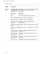


MLD Tab
120
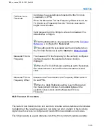
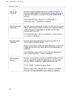
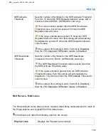
TX Clock Loss
Threshold
Configures the user-definable threshold for the TX Clock
Loss alarm, in PPM.
When the Measured TX Line Frequency Offset exceeds the
TX Clock Loss Threshold, then the TX Clock Loss alarm
begins to accumulate.
Valid range is from 0 to 300ppm, where 0 is disabled. The
default value is 50ppm.
This threshold alarm is only supported when the
Recovered
.
This setting and the associated alarm are disabled when
the TX Clock Reference is set to
Internal
or
Measured TX Line
Frequency
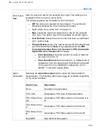
The measured TX line frequency for the currently configured
interface (based on the selected reference clock) is
displayed.
When the TX Clock Reference setting is set to Recovered,
this measurement is derived from the external recovered
clock.
Measured TX Line
Frequency Offset
Measures the Transmission Line Frequency Offset value in
Hz and PPM.
When the Clock Reference setting is set to Recovered,
this measurement indicates the deviation between the
system's Chassis clock and the Measured TX Line
Frequency.
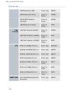
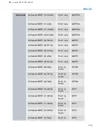
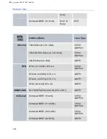
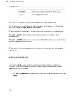
MLD Transmit - Error Alarm
The test unit can transmit errors and alarms to simulate various defects and anomalies
to determine if the receiving equipment can detect an error or alarm in the incoming
signal. Use this screen to configure and transmit Errors and Alarms on all Lanes.
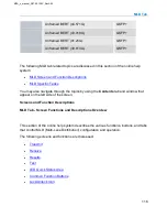
The following table is a quick reference list of the Error and Alarm options available:
MPA_e_manual_D07-00-129P_RevA00
Summary of Contents for MPA
Page 2: ...MPA_e_manual_D07 00 129P_RevA00...
Page 10: ...MPA_e_manual_D07 00 129P_RevA00...
Page 82: ...MPA_e_manual_D07 00 129P_RevA00...
Page 110: ...MPA_e_manual_D07 00 129P_RevA00...
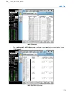
Page 134: ...MLD Tab 134 100G RS FEC Ethernet 400G RS FEC Ethernet MPA_e_manual_D07 00 129P_RevA00...
Page 255: ...Protocol Tabs 255 MPA_e_manual_D07 00 129P_RevA00...
Page 256: ...OTN Tab 256 MPA_e_manual_D07 00 129P_RevA00...
Page 748: ...MPA_e_manual_D07 00 129P_RevA00...
Page 796: ...MPA_e_manual_D07 00 129P_RevA00...


