background image

Spectrum Analysis - Digital Signal

Go back to top


Go back to TOC

7.3.2 Amplitude Measurements

Analog and digital carriers are very different in terms of the signal content and distribution of power over the channel and therefore

need to be measured differently. Signal level meters that are designed to measure only analog carriers will not always measure

digital carriers accurately.

Power is measured either as an absolute level or relative to another power level. Carrier levels are absolute measurements and are

measured in power units, such as dBmV or dBuV. Relative power measurements are C/N, delta audio to video, CTB and CSO, and

are always measured in dB.

Analog TV channel amplitude measurement

The DOCSIS RF Specification recommends that the average power of a downstream digitally modulated carrier be set 6dB to

10dB below what the amplitude of an analog TV channel on the same frequency would be. Before measuring or setting the

amplitude of a digitally modulated carrier, first measure the amplitude of the cable network's analog TV channels.

Digital Carrier amplitude measurement

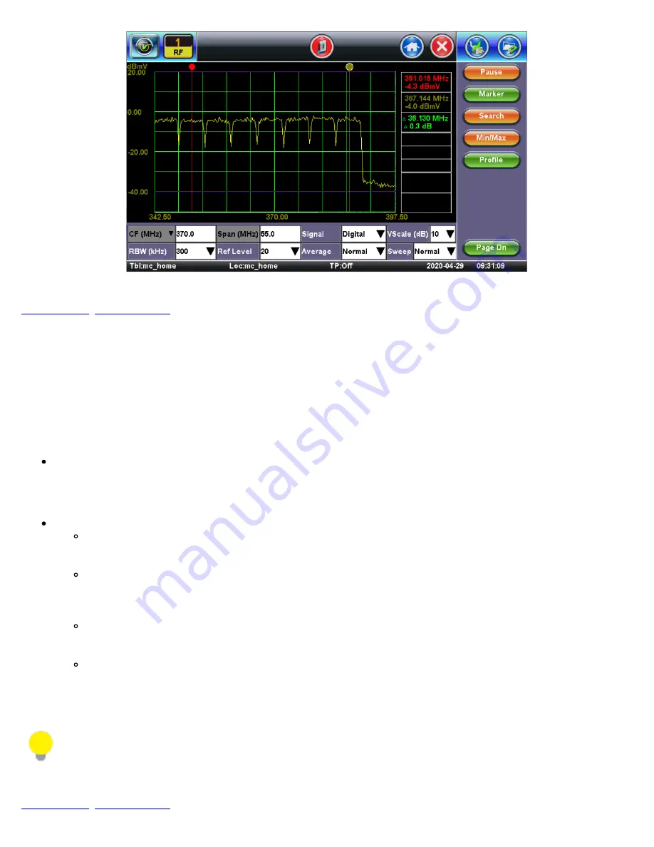
On a digital carrier, the power is spread out more evenly over time and frequency compared to an analog carrier. To

obtain an accurate representation of the power, measure the total power across the frequency band, not just at one

narrow frequency the way an analog SLM measures level.

The 6/8MHz downstream QAM carrier is often referred to as the haystack because it resembles a pile of hay. The

haystack is a continuous MPEG bit stream. The idea is not to just measure the amplitude of the QAM signal, but to

measure the total power contained within the 6 or 8MHz carrier. This is similar to needing to measure the area within

the signal (haystack) instead of its height only.

Using this example, the power has to be measured within one channel or within a specific frequency range. Use

caution when viewing digital modulated signals because the signal level is dependent on the selected measurement

bandwidth (resolution bandwidth).

Spectrum Analyzers typically do not have an IF or resolution bandwidth wide enough to measure a whole digital signal

at once. To overcome this problem, the CX380C makes multiple measurements across the frequency range of the

carrier. The powers of each of these measurements are summed up and the average power of the whole channel is

calculated.


Amplitude Measurements 

Analog TV channel visual carrier amplitude and digitally modulated carrier average power are commonly measured in

decibel millivolt (dBmV), a unit of power expressed in terms of voltage. 

Mathematically, dBmV = 20log (signal amplitude in millivolts/1 millivolt).

Go back to top


Go back to TOC

CX380C User Manual RevA00

Page 37 of 105

Summary of Contents for CX380C

Page 1: ...ithout prior agreement and written consent of VeEX Incorporated as governed by International copyright laws Information contained in this manual is provided as is and is subject to change without noti...

Page 2: ...asic Operation 4 1 Compact Platform Overview 4 2 Keypad 4 3 Touch Screen Display 4 4 Battery 4 5 Connectors and Panels 4 5 1 Test Ports 4 5 2 Utility Ports 4 6 Software Upgrade 5 0 Home Screen and Men...

Page 3: ...tude Measurements 7 3 3 Ingress Measurements 7 4 Cable Modem 7 4 1 Setup 7 4 2 Cable Modem Result DOCSIS 3 0 7 4 3 Cable Modem Result DOCSIS 3 1 7 4 4 OFDM Subcarriers 8 0 Sweep Operations 8 1 Sweep S...

Page 4: ...t Gear Vulnerabilities 9 1 5 About the DI 1000 Fiber Inspection Scope 9 1 6 Fiber Connector Inspection Setup 9 1 7 Capture Tab View 9 1 8 Captured Files Tab 9 2 Optical Power Meter OPM 9 2 1 Setting P...

Page 5: ...bout 11 2 Screen 11 3 Bluetooth 11 4 Power 11 5 Backlight 11 6 Global 11 7 Date and Time 11 8 Remote Access 12 0 File Management 12 1 File Manager Working with Saved Results Profiles Images 12 1 1 Bac...

Page 6: ...ftware is confidential and proprietary of VeEX Inc The software is protected by copyright and contains trade secrets of VeEX Inc or VeEX s licensors The purchaser of this device and or software downlo...

Page 7: ...hod which can save time and improve usability of the product Provides important information needed to use this product and avoid missteps Cautions against and action or inactivity which can hinder pro...

Page 8: ...y VeEX Do not charge or use the battery pack if any mechanical damage is suspected shock impact puncture crack etc Do not continue charging the battery if it does not recharge within the expected char...

Page 9: ...h to 1 8 GHz and optional Return Path to 204 MHz Comprehensive SLM measurements VeCheck Full Band Scan Tilt and Single Channel Advanced Digital Measurements MER BER Equalizer HUM Center Frequency Erro...

Page 10: ...rent Test Results or snapshot in autonamed file with time stamp See File Management Clear History Resets blinking LED reminders of past Errors or Alarms Test results are not affected not used in OTDR...

Page 11: ...o navigate the menus and tabs The unit can also be used in non touch screen mode i e using the Arrow Enter and Escape keys on the keypad to navigate The location of the cursor on the screen is indicat...

Page 12: ...erve its life and to obtain maximum charge The battery is charged during operation provided the unit is connected to the AC Mains using the supplied AC adaptor Removing the battery while the unit is p...

Page 13: ...ht side of the unit A second USB port is located on the top left panel RJ45 10 100Base T Port To access the Ethernet port remove the protective rubber cover on the right hand side of the unit to expos...

Page 14: ...unit and verify that the AC adaptor connected to the unit is charging the battery 5 Insert the USB stick into the port on the right side of the unit 6 Press and HOLD the Save Lock and Power keys simul...

Page 15: ...etup Main Menu Middle Panel Test Applications specific to the test set Single Channel Spectrum Analysis VeCheck OFDM Analysis Tilt Analysis Cable Modem CaLan Sweep Advanced Tools to access more advanc...

Page 16: ...ry power is remains Remote View Indicates the test unit is being accessed remotely File Provides File Storage Information Bluetooth Bluetooth detected Home Provides instant navigation back to the main...

Page 17: ...arrow and select a table from the drop down menu Channel Table Selection Go back to top Go back to TOC Editing or Creating New Channel Tables To create new channel tables or edit existing ones 1 In th...

Page 18: ...Channel Table Selection Main Menu Channel Table List CX380C User Manual RevA00 Page 18 of 105...

Page 19: ...more information about the ReVeal tool see Remote Access and the ReVeal User Manual on www veexinc com Go back to top Go back to TOC 6 2 Locations Location settings are pre set measurement thresholds...

Page 20: ...or Analog and Digital Carriers in the Location Editor screen 4 Tap the checkboxes to apply the threshold settings 5 Once new values have been entered press Save or Save As and type a new name to save...

Page 21: ...To edit measurement thresholds for the preset locations 1 In the left panel tap Setup Main Menu 2 At the bottom tap Loc drop down arrow and select a Location from the drop down menu 3 After editing th...

Page 22: ...the QAM channel is measured and MER and BER performance and other related parameters are displayed The channel to be measured can be entered by either tapping on the Channel box or the Frequency box...

Page 23: ...depending on the picture content e g dark scenes have a higher average power than bright scenes Using sync pulses the carrier is at its peak power and it does not change from scene to scene therefore...

Page 24: ...s quiet then compare with the measured levels during the non sync pulse period Go back to top Go back to TOC 7 1 2 Digital Channel Measurements When testing a digital channel the unit first tries to l...

Page 25: ...EVM Relationship MER determines how much margin the system has available before a failure can be expected A poor MER is not noticeable on the picture up until the point of system failure this is ofte...

Page 26: ...ator problems QAM Power Level numeric in dBmV dBuV MER numeric in dB is an indication of the operating margin of the system Pre BER Pre Error Seconds numeric is the error rate of the incoming signal p...

Page 27: ...the quality and distortion of a digital signal The diagram is an X Y plot of the I In phase and Q Quadrature axis components of the QAM signal and is particularly useful for viewing impairments due t...

Page 28: ...le the middle ones are unaffected Gain compression can result from poor or bad amplifiers IF equalizers and up down converters Gain Compression Broadband or system noise Causes symbol clusters to enla...

Page 29: ...rference Phase noise Also known as Phase jitter in a QAM signal it is caused by transponders in the transmission path or by the I Q modulator Phase jitter is a statistical quantity that affects the I...

Page 30: ...asurement of modulation quality of the transmitted signal before forward error correction Error Vector Magnitude maximum symbol magnitude rms error magnitude X 100 Maximum AC maximum haystack amplitud...

Page 31: ...o reflections amplitude ripple and group delay occurring in the cable network Signals in a cable system can arrive at the receiver before or after the desired signal Signals normally arriving afterwar...

Page 32: ...e set top manufacturer and you should allow adequate margin for degradation The taps on the horizontal axis are proportional to the symbol rate Interpreting the Adaptive Equalizer Display Go back to t...

Page 33: ...l channels which have been recommended or defined for the Scan function should be used when performing Tilt measurements Often Tilt measurements are useful to identify excessive cable lengths at the c...

Page 34: ...requency response To understand the capabilities of the spectrum analyzer and the various elementary settings it is important to have a basic understanding of how a spectrum analyzer operates Referrin...

Page 35: ...e sweeps while a narrow filter is used for narrow sweeps The narrower the RBW setting the better the frequency resolution however narrower filter settings require more measurement time Wider filters a...

Page 36: ...en to Red colors represent highest signal persistence Profile For repeated use of the same spectrum analysis settings tap the PROFILE function key and save the current settings in a profile or recall...

Page 37: ...easure the total power across the frequency band not just at one narrow frequency the way an analog SLM measures level The 6 8MHz downstream QAM carrier is often referred to as the haystack because it...

Page 38: ...pectrum analyzer The sensitivity required to measure low level signals is determined by the measurement setup The spectrum analyzer Input Attenuator and Resolution Bandwidth settings are the key facto...

Page 39: ...rs are briefly outlined as follows IP network layer Data link layer comprising Logical Link Control LLC sublayer conforming to Ethernet standards Link security sublayer for basic privacy authorization...

Page 40: ...rs and a valid IP address on the network Launch the Cable Modem application to access the Setup screen Cable Modem Setup Channel Enter the system s primary DOCSIS channel DOCSIS Mode DOCSIS 3 0 for DO...

Page 41: ...ming step if the CM is not on a channel 2 CM demodulates the DOCSIS signal and looks for a SYNC message 3 CMTS periodically broadcasts Upstream US Channel Descriptors UCD over the DS channel from whic...

Page 42: ...iguration file is valid the CMTS assigns the CM a permanent SID and registers the CM to online status 11 Following registration the CM optionally initiates the activation of the 56 bit DES encryption...

Page 43: ...mentation BPI operating frequency assignments the number of host devices etc Go back to top Go back to TOC 7 4 2 Cable Modem Results DOCSIS 3 0 Ranging tab Provides information about ranging results i...

Page 44: ...k to TOC The Upstream channels provide Upstream Pre Equalization information which can be obtained by tapping on an Upstream UCD number Press the Marker button to highlight a specific pre equalizer co...

Page 45: ...hput test to an actual customer speed test server site To run a VeTest 1 In the Web FTP tab select VeTest from the Mode drop down list 2 Make appropriate selections for Provider and VeTest Server If t...

Page 46: ...een select Pass Through for the Test Mode and press Connect Once the Cable Modem goes online connect a PC to the meter s 10 100 1000T RJ45 port at the top of the unit Traffic will pass through the met...

Page 47: ...ting with DOCSIS 3 1 systems follow these steps 1 For a system that contains both Single Carrier QAM SC QAM and OFDM channels enter the primary SC QAM DOCSIS Channel number and press Connect to go onl...

Page 48: ...tile 2 MER value for the worst 2 of all OFDM Subcarriers Subcarrier Bandwidth Bandwidth setting used for each OFDM Subcarrier Active Subcarriers Number of active Subcarriers in the OFDM channel PLC Ph...

Page 49: ...from the OFDM tab OFDM Details Returns to the OFDM tab Update Scan Reruns the scan for updated measurements Power Scan Runs power signal level scan MER Scan Runs MER measurement Noise Floor Measures n...

Page 50: ...OFDM Subcarrier Scan MER OFDM Subcarrier Scan Noise Floor CX380C User Manual RevA00 Page 50 of 105...

Page 51: ...OFDM Subcarrier Scan MER Noise Go back to top Go back to TOC CX380C User Manual RevA00 Page 51 of 105...

Page 52: ...tion of amplifiers to ensure proper tilt and balancing The CX380C is fully compatible with the CaLan 3010H Headend Sweep Transmitter which injects active sweep points enabling a forward path sweep up...

Page 53: ...closest point to the Headend Save this measurement as reference Move and insert sweep tones at points 4 5 6 and 7 compare results and verify the frequency response and tilt at each point is relativel...

Page 54: ...set the Sweep limits 1 On the Sweep Setup screen tap the Default Location drop down list box and select Manage The Locations screen appears 2 Tap the Location for which you want to set limits and tap...

Page 55: ...matically be set Go back to top Go back to TOC 8 1 2 CaLan Master Profile Set the CaLan Master Profile which contains the communications frequencies between the CaLan 3010H and the CX380C In most case...

Page 56: ...setup is required Forward Sweep Communications Freq MHz Enter the Communications Forward Frequency Return Sweep Communications Freq MHz Enter the Communications Return Frequency Low Pilot Channel Ente...

Page 57: ...ster Profile configured in the Setup screen or using R Server RBW kHz Select 300 kHz for standard sweep Select 100 kHz to go deeper with lower Sweep Transmit Levels Pilots Pilots help determine system...

Page 58: ...load Too much Attenuation can cause loss of communication due to noise or show a noisy sweep trace Pilot level bar graphs and their associated pass fail limits are displayed Digital Level measurements...

Page 59: ...Mode Tap the Return button to switch to the Return Sweep mode Similar to Forward Sweep the test signal is generated by the CX380C injected into the system and measured by the CaLan 3010H at the heade...

Page 60: ...current sweep by pressing the Save key on the test unit s keypad Then identifying information in the Save result as screen Save Reference Tap Reference Load File to see a list of reference files Selec...

Page 61: ...to display only the saved Sweep that is loaded to use for comparison Reference Sweep Mode Reference Only View Tap Both to display both the saved Sweep that is loaded to use for comparison and the Liv...

Page 62: ...ontrols Frequency to display frequency range at the bottom of the screen Start Stop or Center Frequency and Span This controls the display only The sweep transmitter maintains it s sweep frequency ran...

Page 63: ...asurement and 3 points after the measurement are averaged and the result is plotted on the graphic display Averaging is the number of sequential traces that are averaged for each trace Check the Auto...

Page 64: ...o back to top Go back to TOC 9 1 Fiber Scope The Fiber Scope Inspector is an ideal tool for checking fiber optic connectors for dirt and end face quality The handheld probe design enables easy inspect...

Page 65: ...has made the task easier faster and foolproof with the introduction of its patent pending revolutionary Automatic Focus Detection technology Turning ordinary digital fiber scopes like DI 1000 into acc...

Page 66: ...ification Interchangeable tips Most commonly used tips are available FC SC LC ST MTP E2000 including PC APC 60 angled tips among others Compatible with VeEX test sets offering built in Auto Focus Dete...

Page 67: ...age in real time If the markers get in the way of seeing the picture details turn this feature OFF and perform manual analysis Dots Rectangles They are two ways of highlighting the different impuritie...

Page 68: ...r remainders can be seen when comparing images before or after cleaning or polishing Clear All Deletes all the image files in the Captured Files list Delete Deletes any selected files from the Capture...

Page 69: ...de Overlay Enables or disables the mask anomalies identification and analysis Finer From To Identifies the fiber under test Save Report Generates a full report including a table with measurements and...

Page 70: ...s the defects and scratches count by sizes and position used for the evaluation of the Pass Fail criteria according to the IEC 61300 3 35 standard Go back to top Go back to TOC CX380C User Manual RevA...

Page 71: ...e in power readings between the Laser Source LS output being used and what is currently present at the connector after being attenuated by the fiber The results are presented in dB Loss meter requires...

Page 72: ...et Minimum and Maximum amounts of optical power loss that are acceptable for the application or specified for the cable or installation Specify the total amount of attenuation in dB Alternatively sele...

Page 73: ...ameters then press Connect Now that a connection has been established The D for Data in the icon turns green The connection details are displayed in the IP Tools Status tab shown below It will automat...

Page 74: ...ss points AP detected in the 2 4 GHz and 5GHz bands The following information is displayed for each AP SSID name of the AP BSSID MAC address of the AP 802 11 protocol version supported by the AP Max d...

Page 75: ...2 4GHZ Channel 5GHZ Channel 4 Tap the Graph tab of the respective Channel to view the results in a graphical presentation Graph CX380C User Manual RevA00 Page 75 of 105...

Page 76: ...ion for Layer 4 V Test Throughput and V Perf TCP tests using the top 1000BT test port Go back to top Go back to TOC 9 7 HIP Home Installation Process The Home Installation Process can be downloaded to...

Page 77: ...testing Once results are uploaded to R Server it stores and protects the data For more information about R Server go to www veexinc com Go back to top Go back to TOC 9 11 DMM The DMM Digital Multimet...

Page 78: ...or Last configuration IP Address Select from Static or DHCP Static If Static is selected manually enter the IP address parameters local IP Gateway IP and DNS server IP DHCP If DHCP is selected the un...

Page 79: ...with any IP tests If the connection fails go back to the setup screen to verify that the parameters are entered correctly Verify that the Ethernet cable is properly connected on the management port DH...

Page 80: ...enter the Ping repetition rate Ping second up to 10 pings per second Time Out Time to Live TTL in milliseconds Use the alphanumeric keypad to enter the maximum time allowed in ms up to 99999ms between...

Page 81: ...Save as Default Select Default to recall a trace route file or create a new test Destination Enter the IP address or URL of the network device to be detected Time Out Enter the maximum time allowed be...

Page 82: ...If there is no response from a particular hop an asterisk will be displayed Trace Route Result Go back to top Go back to TOC CX380C User Manual RevA00 Page 82 of 105...

Page 83: ...red IP range using the numeric keypad Select the test by placing a check mark in the corresponding box of any of the following ARP Ping Net Wiz Setup Go back to top Go back to TOC 10 2 2 Net Wiz Resul...

Page 84: ...of devices found Number of devices Routers Servers Hosts Net Wiz Results Devices Global Detail displays the Attribute MAC and IP Addresses and Ping test results of each device discovered Net Wiz Resu...

Page 85: ...on Scanning SSID broadcasting and report Signal Strength IP Connection and Ping Test Go back to top Go back to TOC 10 3 1 WiFi Procedure Plug the WiFi adaptor into the USB port Allow at least 30 45 se...

Page 86: ...dit Settings function key appears on the right hand side bar Tap on Edit Settings or Connect AP to change the Encryption Type and enter the WiFi Key Encryption Type Supported encryption types include...

Page 87: ...onnected to Channel WiFi Channel connected to Encryption Encryption type Mode Signal Radio signal level dBm Link quality score Max data rate 802 11 protocols supported WiFi Wiz Connection Status After...

Page 88: ...WiFi Wiz Connect IP Go back to top Go back to TOC CX380C User Manual RevA00 Page 88 of 105...

Page 89: ...y The built in web browser uses the management port IP connection An active IP connection can be established either through Ethernet WiFi or datacard ports The web browser defaults to VeEX s website U...

Page 90: ...of the test set or platform system settings Settings Menu Go back to top Go back to TOC 11 1 1 About The About screen displays information about the software version serial number and MAC address of t...

Page 91: ...and enter keys to start the calibration feature and repeat the procedure Go back to top Go back to TOC 11 1 3 Bluetooth VeEX products support a micro USB Bluetooth adaptor offering wireless connectiv...

Page 92: ...e use an external USB hub to connect additional devices Once detected a Bluetooth icon is displayed on screen Devices The test platform will automatically detect the Bluetooth adaptor once plugged int...

Page 93: ...ss Pair BT to begin the pairing process During the pairing operation you will be prompted to enter a code on the peripheral device PC or Mobile Phone in order to pair successfully Enter the last 4 dig...

Page 94: ...The Power option provides information about current power source and information about the battery gauge Tap on the battery icon on the top bar to bring battery charge and estimated autonomy informati...

Page 95: ...ife To enable the timer check Turn off backlight if device is not used for and with the drop down menu adjust the duration of the idle time before the backlight is turned off Once the timer is active...

Page 96: ...USA user interface version presents SONET DSn application oriented menus while the International setting is more open to all settings Utility Settings General Setting Storage Setting File Name Prefix...

Page 97: ...tion during a long term test Save Screen Shots The following configurations can also be done The compression level of the screen picture Maximum number of screenshots that can be saved Each time the l...

Page 98: ...Capture etc Test Results Management Download results from the test set manage local test results PC HDD generate detailed test reports export to CSV or PDF and print View software options licenses se...

Page 99: ...i test environments VNC clients such as RealVNC are readily available for download for different platforms and form factors including Windows Mac OS Linux iOS Android VNC Service Enable or disable the...

Page 100: ...VNC Viewer Password Prompt Go back to Remote Access Go back to top Go back to TOC CX380C User Manual RevA00 Page 100 of 105...

Page 101: ...set and reduce the number of pages displayed Tap any column header to sort by that specific parameter in ascending or descending order Tap again to change the sorting order Tap Show All to reset filte...

Page 102: ...and Restore Files Bluetooth This function requires a compatible USB dongle For more information see Bluetooth To Export using Bluetooth optional Select the results file then tap BT at the bottom The...

Page 103: ...he maximum of the frequency range for the advanced system scan VeCheck Scan Type Select the channels to scan or use the pre configured channel table Analog C N Offset Sets the offset frequency for the...

Page 104: ...ment The Council of the European Union and the European Parliament adopted Directive 2002 95 EC January 27 2003 to Reduce the use of certain Hazardous Substances RoHS in Electrical and Electronic Equi...

Page 105: ...up and integrate service verification features across copper fiber optics CATV DOCSIS mobile 4G 5G backhaul and fronthaul next generation transport network Fibre Channel carrier metro Ethernet techno...

Reviews: