


Troubleshooting
Replacing the CPU Board
49
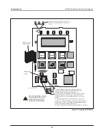
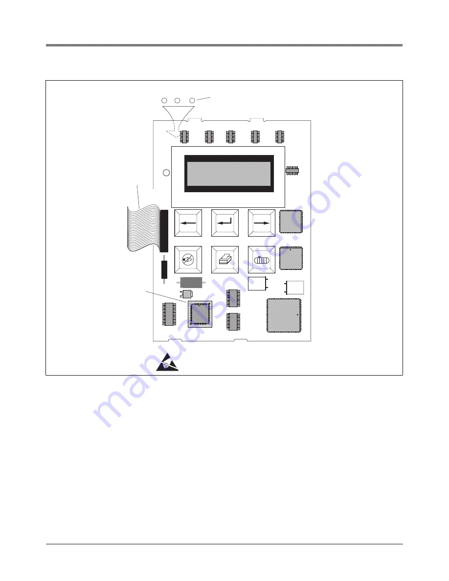
Figure 19. CPU Board Voltage Test Points
2. Attach the anti-static strap to your wrist and to a good ground.
3. Disconnect the CPU cable from the Power Supply board.
4. The CPU board snaps securely into place in the door of the console without the use of screws. There are two tabs on
the top of the board that fit into two slots in the top edge of the door. The bottom of the CPU board snaps in place
between two pairs of detents protruding from the bottom edge of the door. The CPU board is removed by inserting a
straight-slot screwdriver into one of the two indents on the bottom of the board and then gently prying against the
door until the board clears the upper detents, then rotating the board up slightly and toward you to clear the top tabs
from the slots in the door.
5. Replace the CPU board reversing the above steps.
6. Follow the instructions in “TLS-HLD Cold Boot - Initial Power Up” on page 21.
C5
+
Y2
U5
J1
LED1
5V
TLS-50 CPU
Cable to Power
Supply Board
consoles\tls50\cpu.eps
PROM chip
GND
8V
These voltage test points are on the back of
the CPU board (directly behind this upper left
corner)
STATIC SENSITIVE - WEAR
GROUNDED ANIT-STATIC
WRIST STRAP BEFORE
HANDLING THIS BOARD!


