15
EMR
3
- Truck Installations
EMR4 Truck Installation
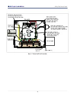
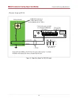
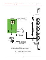
Wiring The Display Head
Figure 9. Display Head Cable Connections
ENS1J-489
ENS1J-489
-L00100
-L00100
BOURNS
BOURNS
VR ENCODER
VRENC
ODER
P/N
P/N
331884-001
331884-001
331933-001331933-001
I.S.
I.S.
Intrinsically-safe inputs from
Interconnect Box, emergency stop switch,
interlock switch, temperature probe,
and optional series 8452 remote pulser
Route cables as shown to
avoid interference with flexible
encoder shaft. Use tie wraps
to attach cables to base.
Pulse encoder
Optional keypad
Encoder shaft
spring
C&C
Jumper
Display head
terminal block
Attach optional remote
pulser, temperature probe,
interlock switch, IB cable and
ESS switch cable shields to
grounding lug on base.
9/64” (3.5mm) max.
Note: Maximum screwdriver
size for attaching wires to
terminal block.
C&C Switch - Removal of corner
bolt releases actuator lever of C&C
switch allowing entry into C&C Mode
#6 Self tapping
screws (3)
Rubber gasket (1)
INTERCONNECT BOX
1000 RPM ENCODER
OPTIONAL KEYPAD
TEMP PRB
INTERLOCK
STOP SW
C & C SW
BLK
GND
RED
PWR
YEL
+
YEL
GND
WHT
+
BLK
GND
GRN
CHA
WHT
CHB
BLK
GND
RED
+5V
WHT
+
BLK
GND
WHT
+
BLK
GND
ORA
KP8
BLU
KP7
YEL
KP6
GRN
KP5
WHT
KP4
BLK
KP3
RED
KP2
NOT
USED
GRN
IB-A
WHT
IB-B


