9
EMR
3
- Truck Installations
EMR4 Truck Installation
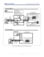
3-Way Safety Valve for Truck LP Gas Systems
• Second Stage Knockoff - When the advance stop (2nd stage knockoff) point is reached, the single flow/relay 2
de-energizes and the single flow/bypass valve closes stopping flow.
Knockoff Control Adjustments - The ‘volume to go’ adjustments are made under RELAY CONTROL in setup
mode. The 1st stage defaults to 5 and the 2nd stage defaults to 0.1. Adjustments to these knockoff points,
particularly the 2nd stage/stop point may be required to accommodate the specific systems dynamics.
3-Way Safety Valve
F
or Truck LP Gas Systems
The 3-Way Safety Valve is not intended for flow control or preset control.
INSTALLING THE 3-WAY VALVE
On the male pipe threads, use a pipe sealant when installing fittings or conduit to either
the valve or the junction box.
1.
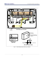
On the valve, install a rigid metal conduit nipple in the threaded opening, provided for the solenoid wiring. Run
the two red wires from the 3-way valve, through the nipple and into a metal junction box. Mechanically attach
the valve/nipple combination to junction box as shown in Figure 5.
Even though the 3-way valve will operate
in any position, it will last longer and perform best if mounted vertically upright (port 3 up)
. Secure the
junction box to the vehicle's frame.
2.
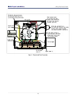
Run a 2-wire shielded cable from the Relay Terminals located at J7 in the IB Box, located in the truck cab, to
the 3-way valve junction box. Pass the cable through a cord grip fitting in one of the J-box openings. Cut off 1-
inch (25.4 mm) of the cable’s shield and jacket, then strip off 1/2-inch (12.7 mm) of each wire’s insulation.
WARNING
The Three-Way Safety Valve is installed and operated in the highly
combustible environment of an LPG tank.
FAILURE TO COMPLY WITH THE FOLLOWING WARNINGS AND SAFETY
PRECAUTIONS COULD CAUSE DAMAGE TO PROPERTY, ENVIRONMENT,
RESULTING IN SERIOUS INJURY OR DEATH.
1. It is essential that you carefully read and follow the warnings and
instructions in this manual to protect yourself and others from serious
injury due to fire, explosion, or electrical shock. LPG systems shall be
installed in accordance with the national standards and regulations that
apply.
2. Comply with all federal, state, and local codes, and other applicable
safety codes. All wiring must comply with standard electrical practices,
the local authority, and the latest editions of the National Electrical Code
(NFPA 70) and other applicable code requirements. All work on LPG
systems must comply with NFPA 58, Liquefied Petroleum Gas Code and
other applicable code requirements.
3. LPG tanks must be depressurized (drained) and free of liquid and
combustible vapors before work begins.
4. Flow control valves connected to the EMR4 must be UL Listed. Also, flow
control valves must be suitable for the intended application, i.e.,
gasoline, fuel oil, LPG and must be rated for use in a Class 1, Division 1,
Group C or Group D Hazardous Location. For LPG applications, such as
propane, each valve must have a minimum pressure rating of 350 psi.
NOTICE


