background image

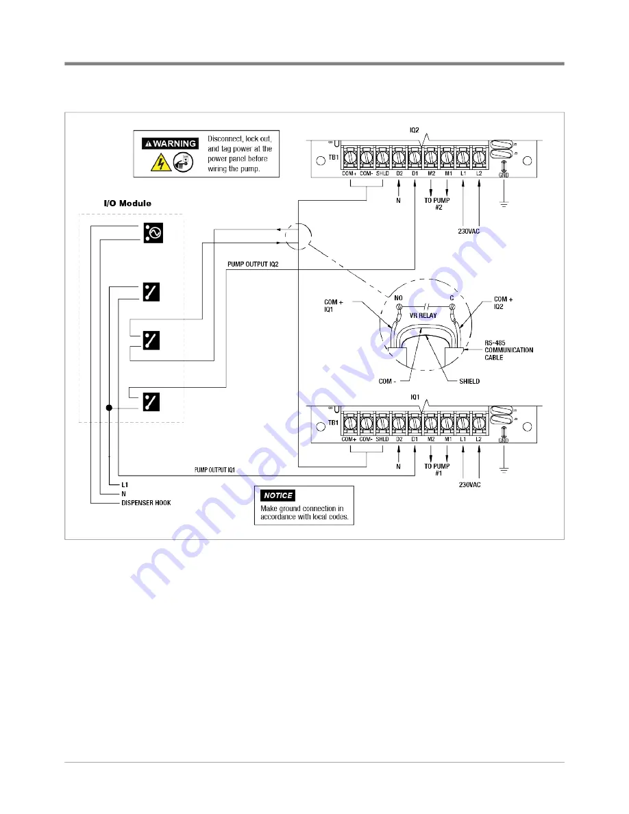
DPLLD Wiring Connections In the Console

Pump Wiring Connections

31

Figure 27.   Manifolded Product Lines - Dual Red Jacket IQ Controllers

Summary of Contents for DPLLD

Page 1: ...DPLLD Site Prep and Installation Guide Manual No 577013 933 l Revision G...

Page 2: ...of Lading to V R Customer Service at 800 234 5350 2 Call V R Customer Service at 800 873 3313 with the specific part numbers and quantities that were received damaged or lost 3 VR will file the claim...

Page 3: ...wiftCheck 8 Red Jacket Standard Pumps DPLLD 14 The Red Jacket Pump 15 Red Jacket Maxxum Big Flo 16 FE Petro Pumps 17 FE Petro High Capacity Pumps 19 FE Petro Variable Speed Pump System Modifications 1...

Page 4: ...tro R Style Precision Check Valve 18 Figure 16 Dip Switch SW2 And Rotary Switch Locations In The FE Petro IST VFC Unit 20 Figure 17 Field Connections Of DPLLD Transducer 21 Figure 18 Epoxy Sealing Pre...

Page 5: ...ractors who will install and setup the equipment discussed in this manual Service Technician Certification Previously known as Level 2 3 Contractors holding valid Technician Certifications are approve...

Page 6: ...ystem This includes information such as maximum number of apparatus specific apparatus allowed in the system maximum cable lengths references to codes proper grounding and so on Control drawings can b...

Page 7: ...ion INJURY Careless or improper handling of materials can result in bodily injury GLOVES Wear gloves to protect hands from irrita tion or injury APPROVED CONTAINERSS Use nonbreakable clearly marked co...

Page 8: ...and others from being struck by vehicles block off your work area during installation or service 4 Do not alter or modify any component or substitute components in this kit 5 Warning Substitution of c...

Page 9: ...hex socket or wrench for tightening it in the pump s leak detector port 4 If you are installing DPLLD into a Red Jacket Standard STP you will need a new Functional Element Warning Tags Turn off tag us...

Page 10: ...ent the DPLLD equipment from detecting line leaks in the area of pipeline downstream from the check valve Manifolded Product Lines Follow these guidelines as you install a DPLLD equipment into multipl...

Page 11: ...n vented check valves may be required depending on pump type and application USM Module to monitor DPLLD transducers I O Module to control site primary and secondary STPs DPLLD Installation Example Fi...

Page 12: ...l connector disconnect bolt 3 Swing electrical connector aside 4 To relieve pressure back out the Functional Element screw or remove the 2 13 Hex Screws on the Packer To Manifold flange interface and...

Page 13: ...go to Step 7 If there is no Stage II vapor recovery install the SwiftCheck valve Figure 4 in the mechanical LLD pump port Thread the DPLLD transducer into the SwiftCheck Valve Do not overtighten the S...

Page 14: ...ransducer must be installed downstream from these devices a monitored containment sump is required There must not be a check valve installed between the SwiftCheck valve and the pump for DPLLD to func...

Page 15: ...h the cord grip and then tighten the nut to ensure a watertight seal Connect and seal the pressure transducer wires to the wires from the TLS console as described in Epoxy Sealing DPLLD Transducer Fie...

Page 16: ...igure 8 to 40 65 in lbs Figure 8 Functional Element Screw Tightening Sequence 15 Be certain all mating surfaces are clean on the body of the Functional Element and the Packer Lubricate the three new f...

Page 17: ...the siphon plug from the new functional element Connect the siphon tubing fitting to the siphon port using fresh UL classified for petroleum non setting thread sealant 19 If applicable open ball valve...

Page 18: ...ngs and install NPT pipe plugs into the respective Line Test and Tank Test ports on the packer Be certain to apply an adequate amount of fresh UL Classified for Petroleum non setting thread sealant on...

Page 19: ...p does not have a Stage II vapor recovery device installed in the pressurized piping remove the 2 NPT plug from line leak detector port Install the DPLLD transducer into the 2 NPT port see Figure 12 S...

Page 20: ...he system is leak free Red Jacket Maxxum Big Flo Disconnect lock out and tag all AC power to the TLS console dispens ers and submersible pumps When servicing equipment use non sparking tools and use c...

Page 21: ...ply sealant in a manner that prevents it from entering and contaminating hydraulic cavities 3 If the pump does have a Stage II vapor recovery device installed in the pressurized piping lubricate the e...

Page 22: ...ealant suitable for the fuel involved Screw the cord grip into one of the openings in the weatherproof junction box Feed the end of the DPLLD transducer cable through the cord grip and then tighten th...

Page 23: ...W2 settings Rotary switch positions The correct hardware and switch settings must be used for the system to detect leaks less than 3 0 gph If the correct hardware and switch settings are not used the...

Page 24: ...The FE Petro IST VFC Unit IST VFC Software Version 1 3 The settings for software version 1 3 are the same as versions 1 1 and 1 2 except that the rotary switch can be set to any position from 1 to 9 T...

Page 25: ...7 Be sure to maintain correct polarity between the color coded or marked field wires and DPLLD transducer wires when making all connections Cut off the transducer shielded ground wire if present flush...

Page 26: ...DPLLD Field Wiring DPLLD Transducers 22 Figure 18 Epoxy Sealing Pressure Transducer Field Connections...

Page 27: ...ing 2 Connect the transducer cable s bare wire shield to one of the ground lugs in the TLS console Figure 19 DPLLD Transducer Wiring To USM Module Pump Wiring Connections The console must be able to d...

Page 28: ...mark each wire to identify its source The dispensers and TLS console must be wired to the same leg of incoming power at the main electrical panel otherwise damage may result to dispensers and console...

Page 29: ...DPLLD Wiring Connections In the Console Pump Wiring Connections 25 Figure 21 Red Jacket Maxxum Big Flo Single Phase Wiring...

Page 30: ...DPLLD Wiring Connections In the Console Pump Wiring Connections 26 Figure 22 Red Jacket Maxxum Big Flo 3 Phase Wiring...

Page 31: ...DPLLD Wiring Connections In the Console Pump Wiring Connections 27 Figure 23 DPLLD Pump Control Diagram For Non Red Jacket Relay Control Box...

Page 32: ...DPLLD Wiring Connections In the Console Pump Wiring Connections 28 Figure 24 Wiring Diagram Manifolded Lines DPLLD Multiple Tanks RJ Relay Control Box Shown In This Example...

Page 33: ...DPLLD Wiring Connections In the Console Pump Wiring Connections 29 Figure 25 DPLLD Pump Control Diagram For Gilbarco Dispenser Isolation Box...

Page 34: ...DPLLD Wiring Connections In the Console Pump Wiring Connections 30 Figure 26 Manifolded Product Lines Dual FE Petro IST VFC Controllers...

Page 35: ...DPLLD Wiring Connections In the Console Pump Wiring Connections 31 Figure 27 Manifolded Product Lines Dual Red Jacket IQ Controllers...

Page 36: ...to RJ Standard pumps with PLLD w o SwiftCheck and to Maxxum Pumps with PLLD and Pressurstat You MUST reset the Functional Element Pressurstat relief pressure as part of the PLLD system installation P...

Page 37: ...o atmospheric pressure by opening a vent screw as in the past The Pressure Offset test procedure described in this step MUST be performed when using new DPLLD transducers with serial numbers of 100 00...

Page 38: ...ing After completing the DPLLD installation the console will not enable dispensing from a line until a 3 0 gph test on the line has been passed In this step as you run the required 3 0 gph test you wi...

Page 39: ......

Reviews: