2
Värmebaronen EP 26E and EP 42E
Content
Notes ....................................................................................... 3
Safety and handling ............................................................... 4
EP 26 - 42 E ............................................................................. 5
Menu - handling ..................................................................... 6
Menus
Handling
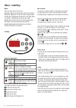
Indicators and buttons
Menu interface
Screen saver
Alarm
Alarm acknowledgement
Menu-User Level .................................................................... 8
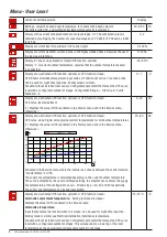
row 0 - Current boiler temperature
row 1 - Configuration set point, display with UTK
row 2 - Display of number of output stages connected
row 3 - Display of current level for external 0 - 10V control signal
row 4 - Display of current level, load guard
row 5 - Display of outdoor temperature with UTK
row 6 - Display alternative temperature, status
row 7 - UTK-curve, level adjustment
row 8 - UTK-curve, inclination
row 9 - Alternative adjustment temperature Alternativ temperature
row 10 - Room sensor current temperature
row 11 - Room sensor, set temperature
row 12 - ECO-mode
Heating curve - UTK ............................................................... 9
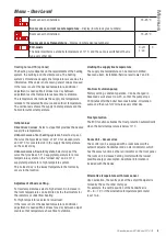
Initial values
Adjustment of basic settings
Supply line temperature limitation
Circulation pump control
Frost protection
Room unit - accessories
Temperature alternatives with room unit
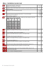
Menu - Installation/service level .......................................... 10
row 1 - Quick increase/reduction
row 2 - Acceleration of activation delay
row 3 - Load guard, main fuse
row 4 - Load guard, stage size
row 5 - Stage limit
row 6 - UTK min limitation of flow row temperature
row 7 - UTK max limitation of flow row temperature
row 8 - UTK room sensor connected
row 9 - UTK room sensor P-factor
row 10 - UTK room sensor I-factor
row 11 - Program version power board
row 12 - Code 21, for access to Advanced service level
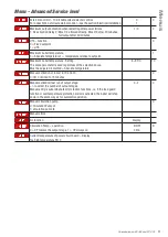
Menu-Advanced Service level ............................................... 11
row 13 - External control 0–10V.
row 14 - Max output activation at restart after power failure
row 15 - UTK – function
row 16 -Max. boiler temperature
row 17 - Max. boiler temperature - setting
row 18 - manual activation of rows 19, 20 and 21
row 19 - Manual activation/test run output stage
row 20 - Manual circulation pump
row 21 - Manual buzzer alarm
row 22 - No function
row 23 - Circulation pump – constant operation
row 24 - Current temperature on power circuit board – Display
Operation and maintenance .................................................. 12
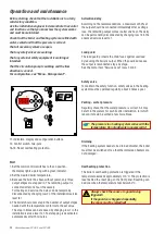
Start
Activation delay
Load guard
Safety valve
Venting - water pressure
Draining
Overheating protection
Over temperature protection
Action in the event of a risk of freezing
Frost protection
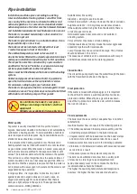
Pipe installation...................................................................... 14
Water quality
Flow direction
Frost protection
Flow requirements
Safety / flow line
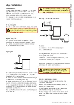
Expansion system
System principles
Open system
Closed system
≤
300 kW och < 110°C
Outlet pipe from safety valve
Electrical installation ............................................................. 16
Output limiting
Power feed
EP 26 E
EP 42 E
Power supply to external unit
Circulation pump
External indicator for the buzzer alarm
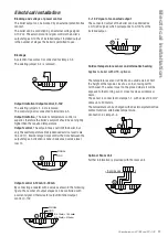
Current Transformers - Load Guard
Blocking and voltage or power control
Blockage
Output limitation/Output control, 0-10V
Output limitation
Output control
Output control 0-10 mA/0-20 mA
0 - 10 V signal of connected output
Outdoor temperature sensor and alternative heating
Optional Room Unit
Wiring diagram - EP 26 E ....................................................... 18
Wiring diagram - EP 42 E ....................................................... 19
Data ......................................................................................... 20
Components ............................................................................ 21
Troubleshooting - Warning, limitation and alarms .............. 22
Limitations
Activation delay
The load guard limits
External limitation/blocking
Manual operation
ECO - mode
Warnings
High temperature around the PCB.
High boiler temperature
Low boiler temperature
Outdoor sensor
Room sensor
Room sensor, handwheel setting
Stop alarm
Boiler temperature sensor
Temperature sensor on circuit board
Low boiler temperature
Buzzer alarm
Low input voltage
Troubleshooting ...................................................................... 23


