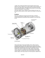
relatively negative multiplier. In addition to allowing the detection of both positive
and negative ions, the off axis conversion dynode eliminates detection of photons
that would be seen by an on axis detector.
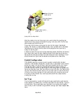
The continuous-dynode electron multiplier consists of a lead-oxide/glass, funnel-
like resistor. A negative voltage of between -800 and -3000V is applied to the
front end of the electron multiplier, referred to as the cathode. The back end of
the cathode is held near ground potential, and is referred to as the anode.
Electrons or ions emitted from the conversion dynode strike the cathode with
sufficient velocity to dislodge additional electrons from the inner curving surface
of the cathode. The increasingly positive potential gradient draws the ejected
electrons into the electron multiplier, further accelerating them in the process.
Because the electron multiplier is curved, the ejected electrons do not travel far
before they again strike the inner surface of the multiplier, resulting in the
emission of more electrons. This configuration produces a cascade of electrons
that is accelerated toward ground potential at the exit end of the cathode.
The anode collects the electrons and passes the resulting ion signal to the ion
amplifier that is mounted on the side of the vacuum manifold directly next to the
multiplier. The ion current is proportional to the total number of ions that the ion
trap ejects. Typically, the voltage applied to the electron multiplier should be
adjusted until the gain is about 10
5
, i.e., until each electron or positive ion that
enters the electron multiplier generates approximately 10
5
electrons.
Vacuum System
The analyzer is contained in a vacuum manifold maintained at a pressure of
10 µTorr. A turbomolecular pump provides the vacuum required. The turbo pump
is backed by a mechanical rotary foreline pump, which also performs the initial
evacuation of the vacuum manifold during pump down. A thermocouple gauge is
used to measure the foreline pressure and an ion gauge to measure the vacuum
manifold pressure.
Vacuum Manifold
The analyzer is contained in a nickel-plated aluminum vacuum manifold that
provides feedthroughs for the various electrical and pneumatic lines that are
required. A top flange feeds the end cap voltages and supplies all the source
electrical connections by way of a printed circuit board feedthrough. A front
flange feeds the CI and Calibration gases and supports the CI ion source
switching mechanism. A side flange provides multiplier connections. All three
flanges are sealed by Viton® O-rings. The manifold has line voltage heaters in its
base to provide heat for bake-out. Insulating material surrounds the manifold to
retain the heat. The turbomolecular pump is mounted horizontally to the rear of
the manifold.
Foreline Pump
The foreline pump has two purposes. The first is reducing the vacuum system
pressure to a level that will allow the operation of the high vacuum
turbomolecular pump. The second is maintaining the vacuum system pressure by
removing the turbomolecular pump’s exhaust gases.
The foreline pump is connected to the turbomolecular pump by a 2.1m (84 in.)
length of 1.9 cm (0.75 in.) ID vacuum tubing. The pump plugs into the rear panel
17 of 127
Summary of Contents for 4000 GC
Page 4: ......
Page 40: ...6 of 127...
Page 77: ...3 Check source connection pins for proper alignment and straighten as necessary 43 of 127...
Page 124: ...90 of 127...
Page 148: ...114 of 127...

