Liquid Level Indicator
4
Installation and Operations Manual
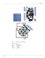
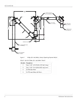
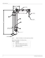
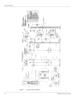
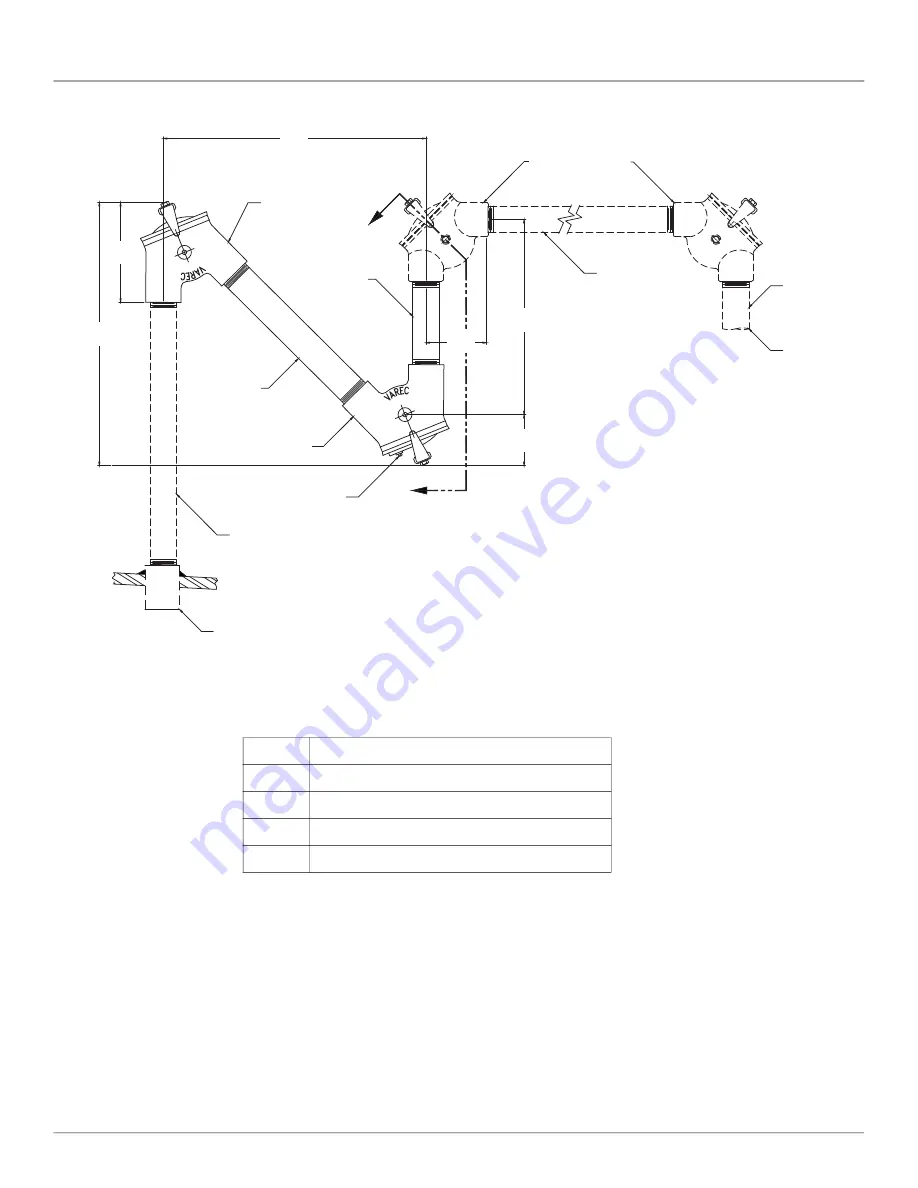
Figure 2:
Oil Seal, 8.5-inch Water Column Operating Pressure Model
1
4
3
2
A
A
90
°
ELBOW FURNISHED
WITH LEVEL INDICATOR KIT
7.70
[196]
20.56
[522]
19.69
[500]
13.69
[346]
4.50
[114]
4.06
[103]
1-1/2 PIPE NPT BOTH ENDS
(BY CUSTOMER)
1/2 NPT DRAIN PLUG
1-1/2 NPT COUPLING
(BY CUSTOMER)
1-1/2 NPT PIPE
(BY CUSTOMER)
TO GAUGEBOARD
OR GAUGEHEAD
1-1/2 NPT PIPE
(BY CUSTOMER)
1
2
3
4
Table 2: Parts for Oil Seal, 8.5-inch Water Column
Item No. Description
1
Pipe, 1-1/2" x 15.50 [394], NPT Ends (Long)
2
Pipe, 1-1/2" x 7.25 [184], NPT Ends (Short)
3
135
°
Sheave Elbow
4
135
°
Sheave Elbow with Drain
Summary of Contents for 6700
Page 2: ......
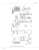
Page 25: ...Installation Varec Inc 17 Figure 8 Half Travel Cone Roof Tank Installation 16 50 419...
Page 39: ...Installation Varec Inc 31 Figure 15 Bolted Tank Installation 16 50 419...
Page 51: ...Installation Varec Inc 43 Figure 20 Severe Service Cone Roof Tank Installation 12 50 318...
Page 70: ...Liquid Level Indicator 62 Installation and Operations Manual...
Page 73: ......


