


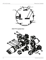


2920 Float & Tape Transmitter
11 Configuration & Calibration — Level, Limits, and Outputs
122
Installation and Operations Manual
Note
To backspace, press Minus to access the back arrow (
). Press Enter to backspace.
9. If the CalLevel requires a two-digit number, press Enter to move to the next digit.
10. Select the second digit using Minus or Plus.
11. Press Enter to select the Return arrow (
) and save the Unit Addr.
12. Press Cancel to exit each menu and return to the Home display.
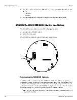
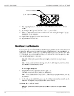
Calibrating Limit Switches
Limit switches are cam-operated SPDT (Single-Pole, Double-Throw) switches that are used to
turn on alarms or other devices when the tank contents reach a predetermined level. The
adjustable cams on the 2920 FTT provide a limited amount of dwell adjustment. The
adjustable dwell can be used to extend the duration of an alarm. Assemblies containing two
or four limit switches are available as an option with the 2920 FTT.
Limit switches are mounted on the 2920 FTT encoder assembly and are mechanically driven
directly from the transmitter drive shaft. Each switch can be set to close or open at any tank
level.
Note
All limit switches are wired to operate as a Normally Closed (NC) circuit at the fac-
tory. If a Normally Open (NO) operation is required, the user must change the wiring at the
switch. See “Wiring Limit Switches”.
Warning!
Obtain a hot permit before removing the transmitter cover with power
applied.
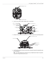
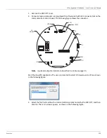
To Calibrate Limit Switches:
1. Remove the transmitter cover.
2. Loosen the slotted coupling on the transmitter drive shaft.
Caution!
Excessively loosening the set screw will cause the coupling to fall. Loose the set
screw only to the extent required to free the encoder.
3. Rotate the 2920 FTT encoder shaft until the level reading to activate the switch is displayed
on the display or at the local host.
Summary of Contents for 2920
Page 2: ......
Page 16: ...2920 Float Tape Transmitter 1 Introduction 6 Installation and Operations Manual...
Page 114: ...2920 Float Tape Transmitter 6 Bi Phase Mark 104 Installation and Operations Manual...
Page 120: ...2920 Float Tape Transmitter 7 MODBUS 110 Installation and Operations Manual...
Page 126: ...2920 Float Tape Transmitter 9 L J TankWay 116 Installation and Operations Manual...
Page 158: ...2920 Float Tape Transmitter 14 Ordering Information 148 Installation and Operations Manual...
Page 193: ......