background image

Vantron

Embedded in your success, Embedded in your better life 

World-leading provider of embedded/IoT products and solutions 


  IBOX66 | User Manual             


31   


       www.vantrontech.com 

4.1


Serial Ports 

IBOX66  offers two  DB9 RS232 connectors (uart4 and uart5) and two DB9 RS232/RS485 

multiplex connectors (uart0 and uart7) for serial communication. 

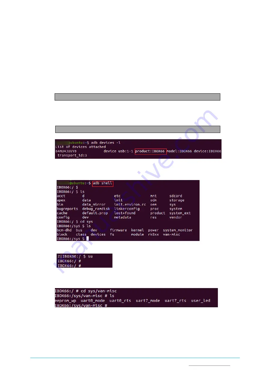
To test if the serial ports function properly: 

1.


Input the following command line in the terminal to install ADB tool; 

$ sudo apt-get install adb -y 

2.


Connect the Device to your Linux host with the USB cable (Type-A male to Type-A male); 

3.


Check if the Device is connected to the Linux host via ADB; 

$ adb devices -l 


4.


Input “adb shell” in the terminal to execute shell commands on the Device; 


5.


Input “su” in the terminal to switch to the root mode; 


6.


Enter the directory of the serial ports as follows: 


Summary of Contents for IBOX66

Page 1: ...dded in your better life World leading provider of embedded IoT products and solutions IBOX66 User Manual www vantrontech com IBOX66 Embedded Industrial Computer User Manual Version 1 0 Chengdu Vantron Technology Co Ltd All rights reserved ...

Page 2: ... your success Embedded in your better life World leading provider of embedded IoT products and solutions IBOX66 User Manual www vantrontech com Revision History No Version Description Date 1 V1 0 First release Sep 22 2022 ...

Page 3: ... STARTED 13 2 1 Hardware Connection 14 2 2 Connecting a Host Computer 17 2 3 Turning on off the Device 18 2 4 First time Setup Guide Android OS only 18 CHAPTER 3 HARDWARE DESCRIPTION 19 3 1 Power input 20 3 2 ON OFF button 20 3 3 Ethernet port 21 3 4 USB 2 0 21 3 5 USB 3 0 21 3 6 HDMI port 22 3 7 Micro SD Micro SIM slots 22 3 8 Audio jack 22 3 9 Serial ports 22 3 10 Reset button 23 3 11 LED indica...

Page 4: ... 4 4 App Installation via ADB Commands Android OS only 34 4 4 1 Prerequisites 34 4 4 2 ADB Setup 34 4 4 3 App installation 36 4 5 Image Flashing in Windows 37 4 5 1 Prerequisites 37 4 5 2 ADB setup 37 4 5 3 Driver installation 37 4 5 4 Image Flashing 39 CHAPTER 5 WARRANTY AND DISPOSAL 40 5 1 Disposal 41 5 2 Warranty 42 Appendix Regulatory Compliance Statement 43 ...

Page 5: ... herein at any time without prior notice An up to date version of this manual is available at www vantrontech com The trademarks in this manual registered or not are properties of their respective owners Under no circumstances shall any part of this user manual be copied reproduced translated or sold This manual is not intended to be altered or used for other purposes unless otherwise permitted in...

Page 6: ...on Technology Inc Address 48434 Milmont Drive Fremont CA 94538 Tel 650 422 3128 Email sales vantrontech com China Office Chengdu Vantron Technology Co Ltd Address 6th Floor 1st Building No 9 3rd WuKe East Street WuHou District Chengdu P R China 610045 Tel 86 28 8512 3930 3931 86 28 8515 7572 6320 Email sales vantrontech com cn Regulatory Information The Product is designed to comply with Part 15 o...

Page 7: ...rwise modify the Product Such action may cause heat generation ignition electronic shock or other damages including human injury and may void your warranty Keep the Product away from heat source such as heater heat dissipater or engine casing Do not insert foreign materials into any opening of the Product as it may cause the Product to malfunction or burn out To ensure proper functioning and preve...

Page 8: ...fore cleaning the Product Do not use spray detergent Clean with a damp cloth Do not try to clean exposed electronic components unless with a dust collector Power off and contact Vantron technical support engineer in case of the following faults The Product is damaged The temperature is excessively high Fault is still not solved after troubleshooting according to this manual Do not use in combustib...

Page 9: ...Vantron Embedded in your success Embedded in your better life World leading provider of embedded IoT products and solutions IBOX66 User Manual 5 www vantrontech com CHAPTER 1 INTRODUCTION ...

Page 10: ...processor developed by Rockchip With 4GB memory and 32GB eMMC storage it features quick access to data and ultra large capacity As such it is capable of dealing with huge volume of data in a timely manner As IBOX66 provides rich interfaces a wide choice of peripherals can be connected for extended applications including barcode scanners cameras barcode printers and keyboard plates It also supports...

Page 11: ...refully packed with special attention to quality However should you find any component damaged or missing please contact your sales representative in due time Accessories 1 x IBOX66 1 x Power adapter 1 x Power cable 1 x Wi Fi BT antenna 2 x 4G LTE antenna Optional Actual accessories might vary slightly from the list above as the customer order might be different from the standard configuration opt...

Page 12: ... Audio 1 x 3 5mm Combo audio jack Speaker 1 x Speaker connector Camera 1 x MIPI CSI 2 2 x 10 x 2 0mm I Os Serial port 2 x RS232 DB9 Connector 2 x RS232 RS485 DB9 Connector USB 4 x USB 2 0 Type A USB OTG supported 1 x USB 3 0 SIM slot 1 x SIM card slot GPIO 8 x GPIO 3 3V Watchdog Supported RTC Supported Expansion Mini PCIe 1 x Mini PCIe for LTE module System Control Button 1 x ON OFF button 1 x Res...

Page 13: ... BT5 0 AP6256 802 11 a b g n ac UART1 IBOX66 Temperature 0 60 WiFi BT ANT USB_OTG0 5W Speaker x2 L R SGM6132 POWER KEY 3 3V DC To system 5V 1x4x2 54mm MAIN BOARD LPDDR4 1024M 32b MiniPCIe 4G ANT MIC I2S1 MICRO SIM EC200 RS485 232 2 RS232 2 USB2 0 HUB USB2 0 3 Type A USB2 0 USB2 0 USB3 0 Type A USB3 0 USB2 0 Type A OTG SGM6132 12V 24V DC for LCD 5V DC for Peripheral SGM6132 3 3V DC for Peripheral D...

Page 14: ... www vantrontech com 1 5 Product Layout 1 5 1 Front view 1 5 2 Back view USB 3 0 Type A Ethernet jack Audio jack Micro SD SIM slots OTG supported 4G master antenna HDMI USB 2 0 Type A ON OFF button OTG switch DC in Installation bracket Installation bracket RS232 RS485 RS232 Installation bracket Installation bracket LED indicator Wi Fi BT antenna ...

Page 15: ...ading provider of embedded IoT products and solutions IBOX66 User Manual 11 www vantrontech com 1 5 3 Left side view 1 5 4 Right side view 4G diversity antenna RS232 MIPI DSI LVDS Backlight connector MIPI CSI eDP Backlight connector Grounding screw Speaker connector GPIO ...

Page 16: ...rs have the option of Linux operating system 1 7 Mechanical Dimensions 160mm x 110mm x 30mm Enclosure only 195mm x 110mm x 30mm With installation bracket 1 8 Power Supply and Consumption IBOX66 works with 12V 24V 3A DC power input supplied by a DC connector The power consumption of IBOX66 is about 15W It should be pointed out that the power consumption is largely dependent on the RAM storage capac...

Page 17: ...Vantron Embedded in your success Embedded in your better life World leading provider of embedded IoT products and solutions IBOX66 User Manual 13 www vantrontech com CHAPTER 2 GETTING STARTED ...

Page 18: ...re you proceed with the configuration of IBOX66 follow the steps below to finish hardware connection 1 Position the Device on a desired place for instance a wall or a desktop 2 Align the screws M4 x 6 M4 x 8 recommended to the screw holes reserved on the mounting bracket and mark the position of the screws on the wall or the desktop 3 Drill four screw holes on the marks made in the prior step ...

Page 19: ...trontech com 4 Place the Device back and adjust the position of the bracket if needed then use a screwdriver to tighten the screws and secure the device 5 Insert an active SIM card and a Micro SD card if any into the corresponsive slots with the gold colored contacts facing down 6 Install the antennas to the antenna connectors and tighten the connectors ...

Page 20: ...User Manual 16 www vantrontech com 7 When necessary plug one end of an Ethernet cable into the Ethernet jack of IBOX66 and the other to a live Ethernet port 8 Connect the female connector plug of the power adapter to the power connector of IBOX66 and the round end to the adapter 9 Plug in the power connector to power on the Device ...

Page 21: ...nected and adapter connectors are sometimes needed HDMI interface for illustration here 2 Connect the mouse and keyboard to the USB interfaces on the Device for easier operation 3 To use the Device as an ADB device dial the OTG switch up and insert a USB cable Type A male to Type A male into the USB OTG port to connect the Device and the host computer If you connect a touch monitor other than a ho...

Page 22: ...o restart the device 2 Press the ON OFF button once to turn off the display 3 Press the ON OFF button and hold for about 2 seconds to call the power menu and click Power off to turn off the device orderly 4 Press the ON OFF button and hold for about 5 seconds to turn off the device directly 5 When necessary unplug the power adapter from the power connector of IBOX66 or the outlet to force shutdown...

Page 23: ...Vantron Embedded in your success Embedded in your better life World leading provider of embedded IoT products and solutions IBOX66 User Manual 19 www vantrontech com CHAPTER 3 HARWARE DESCRIPTION ...

Page 24: ...pply please take the input voltage of the backlight into consideration when selecting the power supply Specification of the power connector 1 x 3 pin 3 81mm 10A JTC EC501RM 3 81 3P 4 Pinout description Pin Signal Description 1 GND Ground 2 VDC 12V Power input 3 VDC 12V Power input 3 2 ON OFF button Button definition Android OS Action with power connected Description Short press Turn on off the dis...

Page 25: ...lements an Ethernet port Specification RJ45 supporting 10M 100M 1000M Base T The Ethernet connector has two link act LEDs to indicate the working status of the Ethernet 3 4 USB 2 0 IBOX66 offers four USB 2 0 interfaces Type A including one USB OTG on the top right that can switch between host down and device up modes with the red switch next to the USB interfaces When switching the OTG modes pleas...

Page 26: ... card slot supports SIM card hot plugging The 4G LTE module of the Device is AT T and Verizon pre certified and you may consult your sales executive for the module name before applying a SIM card from the carrier 3 8 Audio jack IBOX66 offers a 3 5mm 4 pole combo audio jack supporting headphone and microphone functions 3 9 Serial ports IBOX66 implements two DB9 RS232 connectors uart4 and uart5 and ...

Page 27: ... four LED indicators with definition explained below Indicator name Definition 4G indicator Blinking 4G communication working properly Off Problem with 4G communication USER indicator Refer to 4 3 for the command to enable the LED POWER indicator Solid red System power OK Off Problem with system power SYS indicator Solid green System running properly Off System abnormality If the power indicator i...

Page 28: ...CPU_GPIO4 CPU general purpose input output 5 GND Ground 6 GND Ground 7 CPU_GPIO1 CPU general purpose input output 8 CPU_GPIO5 CPU general purpose input output 9 VCC_EXT_3V3 DC 3 3V external power output 10 VCC_EXT_3V3 DC 3 3V external power output 11 GND Ground 12 GND Ground 13 CPU_GPIO2 CPU general purpose input output 14 CPU_GPIO6 CPU general purpose input output 15 GND Ground 16 GND Ground 17 C...

Page 29: ...negative 2 EDP_TX_D1N eDP differential lane 1 negative 3 EDP_TX_D0P eDP differential lane 0 positive 4 EDP_TX_D1P eDP differential lane 1 positive 5 GND Digital ground 6 GND Digital ground 7 EDP_TX_D2N eDP differential lane 2 negative 8 EDP_TX_D3N eDP differential lane 3 negative 9 EDP_TX_D2P eDP differential lane 2 positive 10 EDP_TX_D3P eDP differential lane 3 positive 11 GND Digital ground 12 G...

Page 30: ...gnal for LED driver 5 GND Ground 6 GND Ground 3 14 Speaker IBOX66 provides an L R speaker connector 1 4 2 0mm that allows connection of a 5W 8Ω speaker Pinout description Pin Signal Description 1 OUTR Class D H bridge negative output for right channel 2 OUTR Class D H bridge positive output for right channel 3 OUTL Class D H bridge negative output for left channel 4 OUTL Class D H bridge positive ...

Page 31: ...CLKP MIPI1_DSI Differential Clock Lane 5 GND Digital Ground 6 GND Digital Ground 7 MIPI1_DSI_DN2 MIPI1_DSI Differential Lane 2 8 MIPI1_DSI_DP2 MIPI1_DSI Differential Lane 2 9 MIPI1_DSI_DN1 MIPI1_DSI Differential Lane 1 10 MIPI1_DSI_DP1 MIPI1_DSI Differential Lane 1 11 MIPI1_DSI_DN0 MIPI1_DSI Differential Lane 0 12 MIPI1_DSI_DP0 MIPI1_DSI Differential Lane0 13 LVDS_MIPI0_DN3 LVDS MIPI_DSI Different...

Page 32: ...GND Digital Ground 26 GND Digital Ground 27 LVDS_PWR Power Supply 28 GND Digital Ground 29 LVDS_PWR Power Supply 30 LVDS_PWR Power Supply 31 GND Digital Ground 32 GND Digital Ground BL2 connector pinout description Pin Signal Description 1 LCD_BLK LCD Power Supply for LED Driver 2 LCD_BLK LCD Power Supply for LED Driver 3 LCD_BKLT_EN LED Driver Enabling 4 LCD_BKLT_PWM PWM Signal for LED Driver 5 G...

Page 33: ...3P MIPI CSI differential lane 3 positive 5 GND Digital ground 6 GND Digital ground 7 MIPI_CSI_RX_D0N MIPI CSI differential lane 0 negative 8 MIPI_CSI_RX_D1N MIPI CSI differential lane 1 negative 9 MIPI_CSI_RX_D0P MIPI CSI differential lane 0 positive 10 MIPI_CSI_RX_D1P MIPI CSI differential lane 1 positive 11 MIPI_ CSI_RX _CLK0N MIPI CSI differential clock lane negative 12 I2C2_SCL I2C serial port...

Page 34: ...Vantron Embedded in your success Embedded in your better life World leading provider of embedded IoT products and solutions IBOX66 User Manual 30 www vantrontech com CHAPTER 4 SOFTWARE DEFINITION ...

Page 35: ...erial communication To test if the serial ports function properly 1 Input the following command line in the terminal to install ADB tool sudo apt get install adb y 2 Connect the Device to your Linux host with the USB cable Type A male to Type A male 3 Check if the Device is connected to the Linux host via ADB adb devices l 4 Input adb shell in the terminal to execute shell commands on the Device 5...

Page 36: ...oducts and solutions IBOX66 User Manual 32 www vantrontech com 7 Check if a serial port uart0 for instance can write and read data 8 For the multiplex connectors input the following command lines to wake up the port uart0 for instance echo 1 uart0_mode uart0 wake RS485 echo 0 uart0_mode uart0 wake RS232 ...

Page 37: ...d as set out in step 1 in 4 1 and execute adb shell command in the terminal to prepare for GPIO debugging 2 Input the following commands to enter the directory of the GPIO and check GPIO nodes cd sys class gpio sys class gpio ls 3 Run cat d gpio command to view the details of the ports 4 Use the following commands to enter a specific GPIO port GPIO108 for instance and test if it can read and write...

Page 38: ...e used for the installation are available in the product release package provided by Vantron 4 4 1 Prerequisites IBOX66 running Android operating system A host computer running Windows 7 or later A USB cable Type A Male to Type A Male 4 4 2 ADB Setup 1 Follow the steps in Section 2 2 to connect the host computer and the Device with the USB cable 2 Use the cursor and keyboard to navigate to Setting...

Page 39: ... User Manual 35 www vantrontech com 5 Press Win R and input sysdm cpl in the dialogue box to open the settings interface 6 Click in sequence Advanced Environment Variables Path Edit and click New in the pop up 7 Copy the path of adb exe as mentioned in step 4 and click OK to confirm 8 Press Win R and input cmd in the dialogue box ...

Page 40: ...When the device information is displayed under the command the Device is an ADB device and you can copy the serial number squared as shown above of the Device for installation of an app 4 Input the following command line to install the apk app adb s device serial number install APK path 5 The installation will be executed after the command line is input and the result of installation will be displ...

Page 41: ...ing Windows 7 or later A USB cable Type A Male to Type A Male 4 5 2 ADB setup Follow the steps set out in 4 4 2 to finish ADB setup If the Device is running Linux system you don t need to turn on the developer options for ADB setup 4 5 3 Driver installation 1 Unzip the release package sent from Vantron and open the folder 2 Navigate to the following directory SW DriverAssitant_vxxx DriverAssitant_...

Page 42: ...se_vxxx RKDevTool to install the RK Device Tool 7 Connect the Device and the host computer via the USB cable Normally a message suggesting the existence of an ADB device will show up at the bottom of the tool window in about 10 seconds 8 Input adb shell in the command prompt so that you can execute shell commands on the Device 9 Enter reboot loader in ADB shell to enter Loader mode and the device ...

Page 43: ...tom 4 5 4 Image Flashing 1 Click Upgrade Firmware tab in the RK Device Tool window the second tab at the top of the window and then Firmware button 2 Select update img from the directory SW Image and click Open and the details of the firmware will be automatically populated in the firmware information box 3 Click Upgrade button next to Firmware button and the device will start to download the imag...

Page 44: ...Vantron Embedded in your success Embedded in your better life World leading provider of embedded IoT products and solutions IBOX66 User Manual 40 www vantrontech com CHAPTER 5 DISPOSAL AND WARRANTY ...

Page 45: ...osal in conformity with local regulations Please ensure that the abandoned batteries are disposed of according to local regulations on waste disposal Do not throw batteries into fire or put in common waste canister as they are explosive Products or product packages labeled with the sign of explosive should not be disposed of like household waste but delivered to specialized electrical electronic w...

Page 46: ... CUSTOMER for non warranty repair VANTRON will provide this service as long as the components are available in the market and the CUSTOMER is requested to place a purchase order up front Parts repaired will have an extended warranty of 3 months Returned Products Any Product found to be defective and covered under warranty pursuant to Clause above shall be returned to VANTRON only upon the CUSTOMER...

Page 47: ...does cause harmful interference to radio or television reception which can be determined by turning the equipment off and on the user is encouraged to try to correct the interference by one or more of the following measures Reorient or relocate the receiving antenna Increase the separation between the equipment and receiver Connect the equipment into an outlet on a circuit different from that to w...

Reviews: