Light Commercial
Heat Recovery Ventilators and
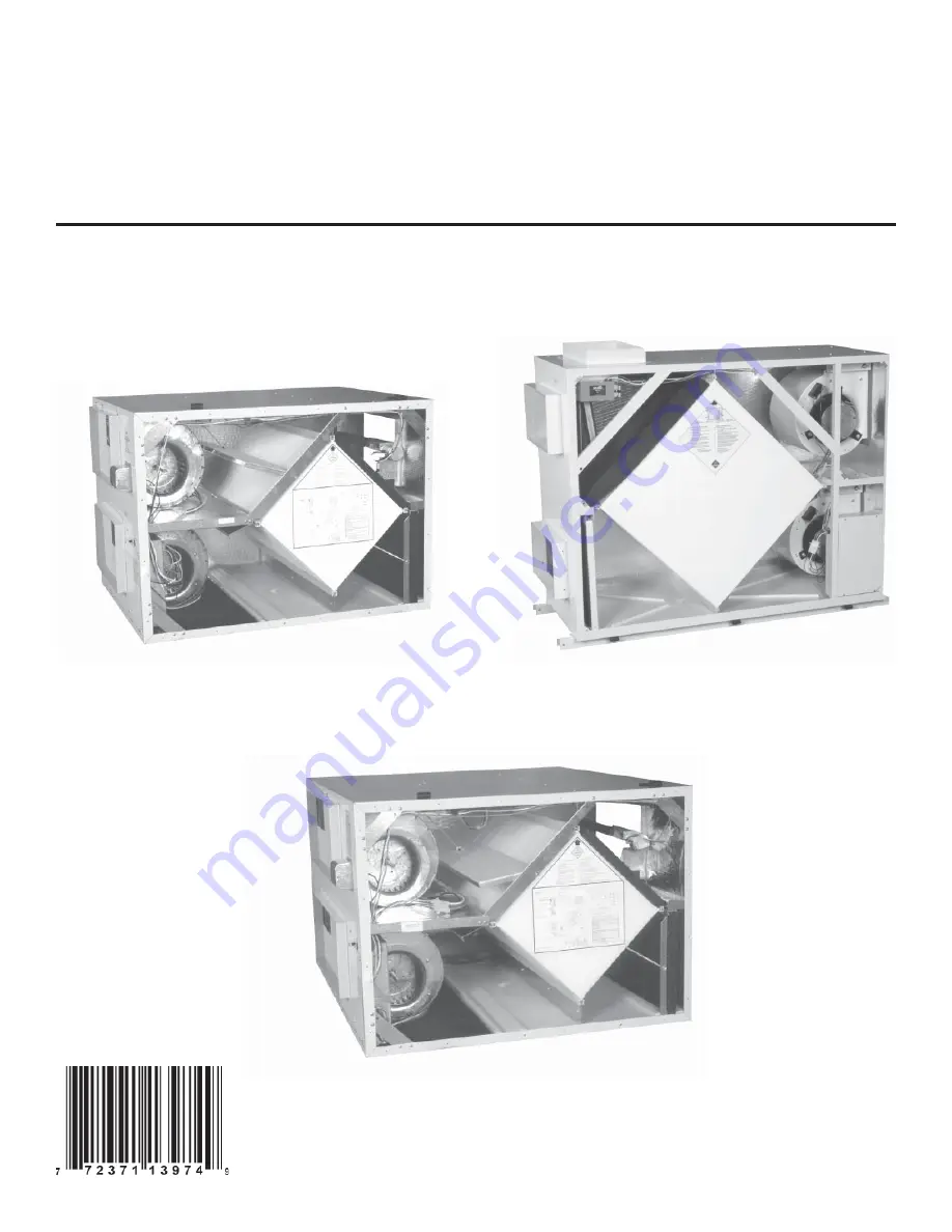
Energy Recovery Ventilators
Installation, Operation
and Service Instructions
VB0002
VB0003
VB0001
207428 rev. 12
6LC, V6LC
7000
12LC, V12LC
Page 1: ...Light Commercial Heat Recovery Ventilators and Energy Recovery Ventilators Installation Operation and Service Instructions VB0002 VB0003 VB0001 207428 rev 12 6LC V6LC 7000 12LC V12LC...
Page 2: ...g Diagrams 10 Appendix B Unit Dimensions 11 15 Appendix C Balancing Dampers Position 16 Appendix D Drain Connections 17 Appendix E Terminal Control Diagrams 18 19 Appendix F Control Box Assembly 6LC V...
Page 3: ...C 14 x 8 356 mm x 203 mm 7000 20 x 8 508 mm x 203 mm NOTE Duct sizes are for connection purposes only Ducts should be sized to keep noise and pressure drop to a minimum The supply and exhaust ducts co...
Page 4: ...ntacts are closed on a call for ventilation or defrost See wiring diagram shown in Appendix E SPEED SELECTION 6LC V6LC 12LC V12LC UNITS ONLY There are three speed settings available with the controls...
Page 5: ...agehighspeedexchange Slideswitchoperation supporting continuous low exchange and continuous high exchange POOL ELECTRONIC TYPE FOR 7000 UNIT ONLY Ideal for pool dehumidification Dehumidistat to engage...
Page 6: ...output across the WHITE BLACK wires If 120 volts can be measured at the motor replace the motor If 120 volts cannot be measured at the motor check pins J1 9 at the printed circuit board WARNING Discon...
Page 7: ...er Optional MEF 6LC V6LC 12LC V12LC unitary Ref Part No Description L 1808130 PCB Electronic 6LC V6LC 12LC V12LC 7000 202382 Thermistor 6LC V6LC 12LC V12LC 7000 500025914 Relay SPDT 120 VAC 1 HP 30 A...
Page 8: ...t I 1607456 DrainFitting6LC V6LC 12LC V12LC 7000 unitary Ref Part No Description J 63342 Filter Optional MEF 6LC V6LC 12LC V12LC unitary K 1808130 PCB Electronic 6LC V6LC 12LC V12LC 7000 202382 Thermi...
Page 9: ...LC V6LC 12LC V12LC 7000 63117 Transformer 7000 63345 RelayDPDT120VAC 1 2HP 15A 120VAC 7000 6LC V6LC 12LC V12LC 066161 Fuse Holder 6LC V6LC 12LC V12LC 7000 066169 Fuse 0 5 A 250 V Time Delay 1 25 MDL 7...
Page 10: ...show standard unit configuration For units with the reversed door option the door will be located here Reinforced Rubber Strap VD0002A Recirculation Module Factory Installed Recirculation Module Fact...
Page 11: ...BOX A MINIMUM OF 15 000 381 CLEARANCE FROM ANY OBSTRUCTION IS REQUIRED FOR REMOVAL OF HEAT RECOVERY CORES FANS ETC THE ACCESS DOOR CAN BE REMOVED FROM CABINET WITH ONLY 2 000 51 OF CLEARANCE CONTROL...
Page 12: ...5 15 00 381 Access Door Core Reversed Door Option Control Plate A minimum of 12 00 305 clearance from any obstruction is required for removal of control box A minimum of 15 00 381 clearance from any o...
Page 13: ...NTROL BOX A MINIMUM OF 15 000 381 CLEARANCE FROM ANY OBSTRUCTION IS REQUIRED FOR REMOVAL OF HEAT RECOVERY CORES FANS ETC THE ACCESS DOOR CAN BE REMOVED FROM CABINET WITH ONLY 2 000 51 OF CLEARANCE EXH...
Page 14: ...above diagram A minimum of 12 00 305 clearance from any obstruction is required for removal of control box A minimum of 15 00 381 clearance from any obstruction is required for removal of heat recover...
Page 15: ...NG RETURN AIR CONDENSATE DRAIN SUPPLY AIR 3 625 92 2 000 51 14 000 356 1 875 48 3 750 95 40 500 1029 8 000 203 12 250 311 8 000 203 15 250 387 B A 2 000 51 Line Voltage In A minimum of 12 00 305 clear...
Page 16: ...erse Door Option Exhaust Air From Building Fresh Air From Outdoors Min 8 203 mm Optional Canvas Vibration Isolator Gravity Backdraft Damper for recirculation defrost option only Min 12 305 mm Exhaust...
Page 17: ...Slope drain lines minimum 1 4 per foot Min 1 25 mm Min 3 76 mm Plastic drain fitting To drain Copper or plastic pipe VO0002A 7000 Min 3 76 mm Min 1 25 mm 3 4 NPT coupler Water trap Min 4 102 mm Min 4...
Page 18: ...6LC 12LC and V12LC units 2 Pool Plus Wall Control with fan mode selection dehumidistat control and high speed recirculation mode for 7000 unit The remote wall controls work with the microprocessor ele...
Page 19: ...Timer 1 M 2 3 4 5 JUMPER CLASS 2 VOLTAGE NOTE Connections are all dry contacts except wall control and 24VAC power supply Use of 24VAC circuit requires isolating contacts ex thermostat to prevent inte...
Page 20: ...8 F 20 C 73 F 23 C 55 F 13 C 68 F 20 C 73 F 23 C 55 F 13 C 68 F 20 C 73 F 23 C 55 F 13 C 68 F 20 C 73 F 23 C kW kW kW kW kW kW kW kW kW kW kW kW kW kW kW 1250 590 14 6 19 9 21 9 11 2 16 5 18 5 7 8 13...
Page 21: ...29 to 2013 CORE DAMPER NOTE B LOW SPEED NO 1003 1009 NC HIGH SPEED NO 1001 1007 NC DEFROST NO NC 1002 BK BK R BK Y BL BN GN O R W W BL W R W Y Y BLACK BLACK RED BLACK YELLOW BLUE BROWN GREEN ORANGE RE...
Page 22: ...2004 2005 2006 2007 2008 2009 2010 2011 2012 2013 TB2002 TB2002A BK BK R GN GN GN BL BL Y PJ2003 PJ2003 PJ2003 PJ2003 PJ2003 PJ2003 R2004 1 1 3 3 2 2 4 4 6 6 5 5 3 9 K to 1021 INTERLOCK to 1022 REMOTE...
Page 23: ...120 VAC RELAY DPST 120 VAC 1 HP 30 A 120 VAC RELAY DPDT 24 VAC 1 2 HP 15 A 120 VAC FUSE 0 25 A AND FUSE HOLDER MINI PC BOARD TRANSFORMER CONTROL BOX BOM UNIT CONTROL BOX ADDER CONTROL BOX 0341A 6LC V...
Page 24: ...OM BK Y to 1003 1009 HIGH SPEED W R 13 14 CR1030 DEFROST 2 NO 2023 NC 2024 2000 2001 2002 2003 2004 2005 2006 2007 2008 2009 2010 2020 2021 2022 2023 2024 2025 2026 2027 2028 2029 2030 TB2002 TB2002A...
Page 25: ...24 R2004 SN1030 TB1001 QTY 2 1 1 1 1 1 1 DESCRIPTION RELAY DPDT 120 VAC 1 2 HP 15 A 120 VAC FUSE 0 5 A AND FUSE HOLDER FLUSH MOUNT PC BOARD TRANSFORMER RESISTOR 3 9K THERMISTOR 10K OHMS SPLITTER BLOCK...
Page 26: ...w frame Unit stops functioning Electrical supply interrupted Check the unit circuit breaker Air from supply diffusers too cold Imbalance of supply and exhaust air Outdoor temperature very cold Check f...