TS
−
I Special servo drive for hybrid electro-hydraulic system of injection molding machine User Manual
Chapter 2 Installation and connection of servo driver
9
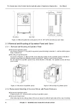
in direction 1 and at the same time lift the cover in direction 2, as shown in Figure 2
−
5.
Removal of upper cover
As shown in Figure 2
−
6, press the left and right sides of the cover forcefully in direction 1, and at the
same time lift the cover in direction 2.
Figure 2
−
5 Removal of lower cover Figure 2
−
6 Removal of upper cover
Mounting of upper cover
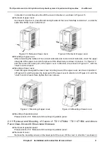
After connecting the cables of main circuit terminals and control circuit terminals, insert the upper
claw grab of the upper cover into the groove of the driver body, as shown in position 1 in Figure 2
−
7,
and then press the lower part of the upper cover in direction 2 as shown in Figure 2
−
7, until the
“crack” sound is heard.
Mounting of lower cover
Insert the upper claw grab the lower cover into the groove of the upper cover, as shown in position 1
of Figure 2
−
8, and then press the lower part of the lower cover in direction 2 of Figure 2
−
8, until the
“crack” sound is heard. Now, tighten the cover screws.
Figure 2
−
7 Mounting of upper cover Figure 2
−
8 Mounting of lower cover
Mounting of operation panel
Please refer to 2.3.1 Removal and mounting of operation panel.
2.3.3 Removal and Mounting of Covers of TS
−
I
−
4T024A
~
TS
−
I
−
4T150A and Above
Power Class Driver with Sheet-metal Enclosure
Removal of operation panel
Please refer to 2.3.1 Removal and mounting of operation panel.
Removal of cover
Remove the mounting screws on the lower part of the cover, lift the cover in direction 1 as shown in
Summary of Contents for TS-I Series
Page 1: ...User Manual TS I series servo drive is introdution V T ...
Page 2: ......


