


AIR N ARC
®
I
-
300 SERIES ALL-IN-ONE POWER SYSTEM
®
SECTION 4: OPERATION
090045-OP_r1
PAGE - 29
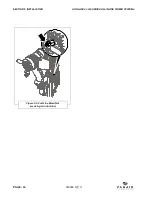
4.4 OPERATING THE
WELDER
Consult
Figure 4-4
. The
variable power
dial
adjusts the welder amperage (0 to 300
amps), or voltage (15 to 40 volts) for the
desired weld heat. Turning the power dial
clockwise increases the amperage or
voltage, and turning the power dial
counterclockwise decreases the amperage
or voltage. The power dial may be adjusted
while welding.
4.4.1 WELDER OPERATING PROCEDURE
4.4.1.1 CC (CONSTANT CURRENT)
MODE
CC (Constant Current) Mode is commonly
referred to as - Stick Welding, Arc Welding,
or Shielded Metal Arc Welding (SMAW).
1. With the engine shut off, insert the twist
lock connections of the work clamp and
the electrode holder cables into the
welder connection ports on the control
panel. For Direct Current Electrode
Positive (DCEP), connect the electrode
holder to the positive (+) port, and the
work clamp to the negative (–) port.
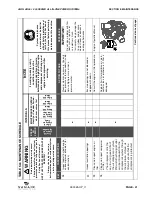
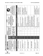
2. Select the appropriate electrode for the
material and process being performed.
See
Table 4A: ELECTRODE
SPECIFICATIONS
for selecting an
electrode.
3. Place the ground clamp on the work
piece and insert the appropriate
welding rod into the electrode clamp.
4. Start the engine (
See Section 4.2,
Machine Start-up and Shutdown
Procedure
).
5. On the control panel, place the CC/CV
switch in CC mode. Place the DC
Charger/Welder switch in welder
mode.
6. Adjust the power dial to the appropriate
amperage setting for the material and
the electrode being used. (See
Table
4A: ELECTRODE SPECIFICATIONS
for electrode amperage ratings). At
anytime during welding, the power dial
may be adjusted to the desired
amperage level.
7. When you strike the electrode against
the material being welded, the engine
will go to high idle and deliver the
selected amperage through the
electrode. Welding can now begin.
8. After a weld has been completed, and
there is no contact between the
WARNING
Before attempting any welding
procedure, the operator must be aware
of general safety practices, and
particularly those pertaining to welding,
as found in
Section 1.4
of this manual.
Figure 4-4: Variable Power Dial Adjustment
B
A
KEY
DESCRIPTION
A
DIGITAL READ
OUT DISPLAY
B
RANGE:
0-300 AMPS
15-40 VOLTS
DANGER
DO NOT weld with the electrode holder
connected to the negative (-) port and the
work piece connected to the vehicle.
Bodily harm and equipment damage may
occur.
NOTE
The amps/volts display will read the set
value for five (5) seconds when the dial is
adjusted, and the actual output value five
(5) seconds after the dial has been
adjusted.
Summary of Contents for AIR N ARC I 300 SERIES
Page 12: ...PAGE X 090045 OP_r1 BLANK PAGE ...
Page 129: ...BLANK PAGE ...


