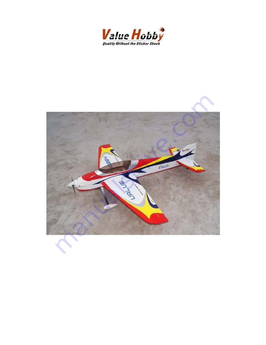
51in Aerobatic Series
F3A Oasis
Almost-Ready-to-Fly
Instruction Manual
Specifications
Wingspan: 50.6 in (1285mm)
Length: 53.1 in (1350mm)
Wing Area: 480 sq in (31sq dm)
Flying Weight: 3.5 lb (1600g)
Page 1: ...51in Aerobatic Series F3A Oasis Almost Ready to Fly Instruction Manual Specifications Wingspan 50 6 in 1285mm Length 53 1 in 1350mm Wing Area 480 sq in 31sq dm Flying Weight 3 5 lb 1600g...
Page 2: ...eserves the right to modify this warranty without notice Value Hobby has no control over the final stages of assembly or the material used for the final assembly No liability shall be assumed nor mate...
Page 3: ...time you take the plane out to the flying field These wrinkles are the result of wood shrinkage and or expansion Balsa wood changes size and shape slightly as it is exposed to varying humidity in the...
Page 4: ...ol 60A PRO Brushless ESC with UBEC 1 Recommended Battery LiPO GForce Elite Series 35C 2200mAh 3S11 1V or 4S14 8V LiPO 1 Prop Size APC 14X7 or APC 13 X6 5 1 servos 17gX1 9gX3 4 Y Harness Universal Serv...
Page 5: ...on Step 1 Locate the hinges from the hardware pack Test fit the four aileron hinges on the aileron Verify the correct position and alignment of the aileron with the wing panel Step 2 Glue each of the...
Page 6: ...Carefully glue each of the four hinges into the wing panel with thin CA Step 4 Move the aileron up and down several times to work the hinges and check for proper movement Step 5 Repeat steps 1 throug...
Page 7: ...bby com 7 Section 2 Aileron Servo Control Horn Installation Step 1 Locate the following hardware Servos and Y Harness need to be purchased separately Step 2 Remove the covering over the aileron servo...
Page 8: ...http www valuehobby com 8 Step 3 Install the servo onto the wing panel Glue the fiberglass horn onto the aileron with medium CA...
Page 9: ...http www valuehobby com 9 Step 4 Install the carbon fiber pushrod and make the final adjustment as shown in the picture Step 5 Repeat steps 1 through 4 for the other wing panel...
Page 10: ...http www valuehobby com 10 Section 3 Rudder Installation Step 1 Insert three hinges in their appropriate slots on the rudder Verify the alignment and glue them with some drops of thin CA...
Page 11: ...http www valuehobby com 11 Step 2 Locate the rudder and carefully glue the hinges with some drops of thin CA...
Page 12: ...Test fit the horizontal stabilizer in the fuselage It should be centered between the left and right side Using the wing tube as a guide measure the distance from the tube to the stabilizer as shown Ma...
Page 13: ...com 13 Step 2 Trace the outline where the horizontal stabilizer joins the fuselage using a marker Step 3 Using the outline from the last step remove the covering over the horizontal stabilizer that go...
Page 14: ...4 Insert in the elevator the four hinges into their appropriate slots and verify the correct position and alignment of the elevator with the stabilizer Then carefully glue the hinges with some drops...
Page 15: ...http www valuehobby com 15 Step 5 Insert carefully the elevator through the fuselage Step 6 Insert carefully the stabiliser into fuselage space Locate the elevator hinges into the stabiliser...
Page 16: ...the elevators 45 degrees up and down make sure the elevator can move freely Then glue the hinges with thin CA Step 8 Slide the carbon fiber wing tube into the fuselage and carefully check the alignme...
Page 17: ...http www valuehobby com 17 Step 9 Once satisfied with the alignment glue the stabilizer onto the fuselage with thin CA...
Page 18: ...http www valuehobby com 18...
Page 19: ...trol Horn Installation Step 1 Locate the items below from the hardware pack The servo and extension are not included and need to be purchased on your own Step 2 Install the servo into the fuselage Glu...
Page 20: ...http www valuehobby com 20 Step 3 Install the carbon fiber pushrod and make the final adjustment as show in the picture...
Page 21: ...trol Horn Installation Step 1 Locate the items below from the hardware pack The servo and extension are not included and need to be purchased on your own Step 2 Install the servo into the fuselage Glu...
Page 22: ...http www valuehobby com 22 Step 3 Install the carbon pushrod and make the final adjustment as shown in the picture...
Page 23: ...aluehobby com 23 Section 7 Tail Wheel Installation Step 1 Cut a 30mm slot on the rudder Drill a hole in the rudder for tail wheel wire This hole position must be precise so the tail wheel wire can be...
Page 24: ...http www valuehobby com 24 Step 2 Secure the tail wheel Carefully apply in the rudder slot a few drops of medium CA as shown in the picture...
Page 25: ...8 Landing Gear Wheels Installation Step 1 Locate the parts of the main landing gear from the hardware pack Step 2 Install the main wheels on the wheel pants as shown below Step 3 Repeat steps 2 for t...
Page 26: ...http www valuehobby com 26 Step 4 Install the landing gear legs into the fuselage with the provided 3mm screws as shown below...
Page 27: ...s motor onto the firewall using the 4 black 3mm allen head screws included in your kit Make sure the motor spins freely Depending on the size of the shaft collar on your motor you may need to remove a...
Page 28: ...he front of the fuselage The cowl mounting screws are screwed into these plywood pieces In order to know where these plywood rectangles are after we install the cowl tape small pieces of paper over th...
Page 29: ...make small holes through the paper strips into the cowling This locates the cowl screws accurately so that they will screw into the plywood Use the 4 small remaining wood screws to mount the cowl Ste...
Page 30: ...http www valuehobby com 30 Section 11 Wings installation Step 1 Install the Wings as shown below...
Page 31: ...we recommend the following throws High rate 40 up down Normal flight D R 30 Expo 30 Snap D R 40 Expo 50 Spin 3D D R 100 Expo 95 For the RUDDER we recommend the following throws High rate 40 left right...
Page 32: ...http www valuehobby com 32 Finally Enjoy Your F3A Oasis have a nice flight...