Technical Instruction
ingal eps
Technical instruction
seesaw poles
page 1
seesaw pole Operation
1.0
introduction
1.1
The ingal eps mid hinged seesaw range of street lighting and Floodlighting columns provides the user with a simple, safe and effective method
to maintain luminaires at ground level. it is most suitable where height and location factors present constraints for luminaire maintenance work to
be carried out effectively.
1.2
as the column is accurately balanced, it is ideal for single-handed maintenance work and requires only a length of rope and an allen key for
operation (refer note after clause 3.1).
2.0
assembly of seesaw Columns
2.1
if the column is unassembled, assemble sections in accordance with
8.6.02 Pole Assembly and Installation for Floodlight Poles
as applicable to the
overall length of the seesaw. incorrect assembly of columns could cause serious damage to the public and private property. it is the installer’s
responsibility to ensure the sections are fitted together correctly. note: after joining, slip joints above the hinge are to be secured with tek screws
(refer to
8.6.02 Pole Assembly and Installation for Floodlight Poles
). For advice, contact your local ingal eps office.
2.2
after assembly of the column and whilst the column is on the ground, attach all fittings to the top of the column; headframe, crossarms, luminaires,
lighting arrestors…etc.
Note: Headframes and crossarms should be attached to the chain link at the top of the column, via the chain and “D” shackle provided, as a safety
precaution should the headframe or crossarm work loose.
2.3
Columns are supplied with a balance weight to counteract the weight of the top fittings, so prior to standing the column
all fittings must be
attached
for the seesaw system to function effectively.
Note: 1. Some Seesaw columns do not require a balance weight, as the weight of the apron only is sufficient to counter balance the top weight.
2. Attachments (eg. luminaires, crossarms, banners etc.)
must not
be changed/modified from the original specification at time of order unless
consultation has been provided by INGAL EPS. Failure to consult INGAL EPS prior to changes may result in damage to property or serious injury
and will void INGAL EPS’ liability.
2.4
ensure that there is sufficient slackness in the electrical cables running up the inside of the column to allow for lowering of the column and that the
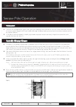
cables do not foul the balance weight. Cable guides are included adjacent to the balance weight recess (refer to figure 1).
Note:
25m, 27m and 30m columns have stiffening plates at the hinge position. It is important that electrical cables run at the centre of the
column between the two stiffening plates and that there is a minimum of 1 metre slack in the cable length.
Figure 1.
Cables
Cable
guides
Doc. No:
8.6.03
Revision:
0
Date:
7-8-2013
Replaces: 8.4.2.3


