


804
Thermo AC/DC
8 Repairs
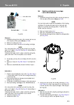
Fig. 803 (Sheet 1) Components removal/installation
1
2
3
4
5
6
7
8
9
10
11
12
13
14
15
16
A Blatt 2
C Blatt 2
D Blatt 2
17
B Blatt 2
5 +1 Nm
10 +1 Nm
2 +0,5 Nm
8 +1 Nm
10 -1 Nm
16 +1 Nm
1
Hood
2
Hood screw (2)
3
Stabilizer
4
Cable gland power supply
5
Cable gland control cables
6
Nut (2)
7
Washer (2)
8
Screw (2)
9
Washer (2)
10 Separation disk
11 Stay bolts (2)
12 Gasket ring (2)
13 Connecting pice
14 Washer
15 Grounding screw
16 Small distribution board
17 Housing
NOTE:
The small distribution
board (17) components
differ depending on
heater model.
1,5 -0,3 Nm
Summary of Contents for Thermo AC 070
Page 47: ...memos...


