- 40 -
damage.
5. Ensure that the ground wire is always properly connected.
6. The filter must be maintained on a regular basis in order to ensure clean and healthy
water to protect the heat pump from damaging.
7. Keep inspecting power and electrical components’ wiring to make sure their normal operation.
8. All the safety protection devices have been set up; please refrain from changing these
settings. If any changes are needed, please contact the authorized installer/agent.
9. If the heat pump is installed under roof without a gutter, ensure that all measures are
taken to prevent excessive water from flooding the unit.
10. Do not use this heat pump if any electrical part has been in contact with water. Contact
an authorized installer/agent.
11. If the increase of power consumption is not due to colder weather, please consult with
the local authorized installer/agent.
12.
Please turn off the heat pump and disconnect it from the mains power supply, when not
in use for a prolonged period of time.
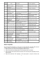
Troubleshooting
Use the following troubleshooting information to resolve issues/problems with your
EVI DC Inverter heat pump.
WARNING — RISK OF ELECTRICAL SHOCK OR ELECTROCUTION.
Ensure that all high voltage circuits are disconnected before commencing heat pump
installation. Contact with these circuits could result in death or serious injury to users,
installers or others, due to electrical shock and may also cause damage to property.
DO NOT
opens any part of the heat pump as this may result to electrocution.
1. Keep your hands and hair clear of the fan blades to avoid injury.
2. If you are not familiar with your heater:
a)
DO NOT
attempt to adjust or service the unit without consulting your authorized installer/agent.
b)
PLEASE
read the complete Installation and/or User’s Guide before attempting to operate
service or adjust the heater.
IMPORTANT:
Turn off the mains power supply to the EVI DC Inverter heat pump prior to attempting
service or repair.
Summary of Contents for V1 Series
Page 9: ...8 V1 18 V1 23 V1 28 V1 35...
Page 10: ...9 Exploded view V1 08...
Page 11: ...10 V1 13...
Page 12: ...11 V1 18 23...
Page 13: ...12 V1 28 35...
Page 16: ...15 Figure 2 Figure 3...
Page 18: ...17 Figure 7 Figure 8...
Page 20: ...19 Figure 11 Figure 12 Figure 13...
Page 23: ...22 Electrical Wiring Diagram 1 Single phase system V1 08...
Page 24: ...23 2 Three phase system V1 13 18 23...


