Valco baby Heat Rite 225 Owner'S Manual And Instructions Download Page 1

Congratulations!

You have purchased the finest agricultural building heater available. 

Your new VAL-CO heater incorporates the benefits from the most experienced
manufacturer of heating products using state-of-the-art technology.

We, at VAL-CO, 

thank you

for your confidence in our products and 

welcome any suggestions or comments you may have......call us, 
at 419-678-8731.

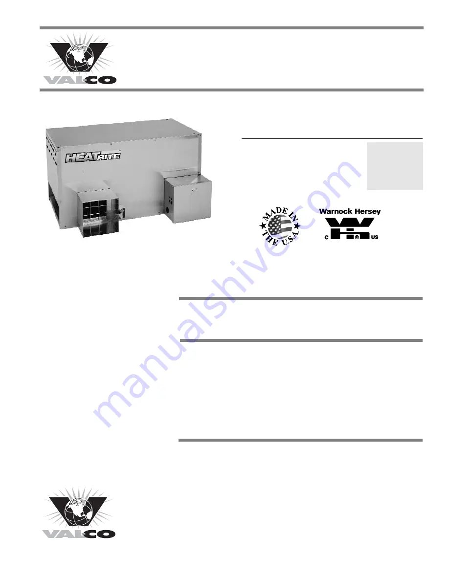
Owner's Manual and Instructions

Agricultural Animal Confinement Building Heaters

F150-81512-A

IGNITION OUTPUT

MODEL

TYPE

(BTUH)

60,000

Heat Rite

Pilot

225,000

Available in

either L.P. Vapor

Withdrawal or

Natural Gas

Configurations.

210 East Main Street, P.O. Box 117, Coldwater, OH  45828 USA

(419) 678-8731

Summary of Contents for Heat Rite 225

Page 1: ... at VAL CO thank you for your confidence in our products and welcome any suggestions or comments you may have call us at 419 678 8731 Owner s Manual and Instructions Agricultural Animal Confinement Building Heaters F150 81512 A IGNITION OUTPUT MODEL TYPE BTUH 60 000 Heat Rite Pilot 225 000 Available in either L P Vapor Withdrawal or Natural Gas Configurations 210 East Main Street P O Box 117 Coldw...

Page 2: ...agricultural confinement building heater CAN 1 2 20 and is listed and approved for Canadian installations as a gas fired brooder CAN 1 2 21 Gas Fired Appliances for Outdoor Installation CAN CGA 2 17 Gas Fired Appliances for use at high altitudes NEC 547 National Electric Code Agricultural Buildingss manual Agricultural B Building H Heaters Agricultural building heaters are intended only for instal...

Page 3: ...operty damage or loss from fire or explosion Asphyxiation due to lack of adequate air supply or carbon monoxide poisoning Electrical shock Read this Owner s Manual before installing or using this heater Only properly trained service people should repair or install this heater Save this Owner s Manual for future use and reference Owner s Manuals and replacement labels are available at no charge For...

Page 4: ... VAL CO distributor or VAL CO for assistance or if you have any questions about the use of the equipment or its application VAL CO has a policy of continuous product improvement It reserves the right to change specifications and design without notice SECTION PAGE General Information 3 Heater Specifications 4 Safety Precautions 5 Installation Instructions General 7 Ventilation 8 Air Diverter Instal...

Page 5: ...tural Gas Gas Gas Gas M Mo od de el l Ventilation Air Required to Support Combustion Burner Manifold Pressure Electrical Supply Volts Hz Phase Amp Draw Dimensions L x W x H in inches Minimum Safe Distances From Nearest Combustible Materials STARTING CONTINUOUS OPERATION Motor Characteristics Fuel Consumption Per Hour Inlet Gas Supply Pressure Acceptable at the Inlet of the Heater for Purpose of In...

Page 6: ...hing Symptoms of improper combustion affecting livestock can be disease lower feed conversion or death Asphyxiation Hazard Some p people c cannot s smell w well S Some p people c cannot smell t the o odor o of t the m man m made c chemical a added t to propane LP o or n natural g gas Y You m must d determine i if y you can s smell t the o odorant i in t these f fuel g gases Learn to recognize the ...

Page 7: ...terior of the heater and it s components After external washdown do not operate this heater until it is completely dry In any event do not operate the heater for at least one hour after external washdown 5 For safety this heater is equipped with manual reset high limit switches and an air flow switch Never operate this heater with any safety device that has been bypassed Do not operate this heater...

Page 8: ... within 6 ft of the heater it serves 9 Check all connections for gas leaks using approved gas leak detectors Gas leak testing is performed as follows Check all pipe connections hose connections fittings and adapters upstream of the gas control with approved gas leak detectors In the event a gas leak is detected check the components involved for cleanliness and proper application of pipe compound b...

Page 9: ...vided in accordance with national provincial local codes of CAN CGA B149 if local code requirements do not exist CAN CGA B149 requires the building have ventilation of not less than 3 cfm per 1 000 BTUH input of the heater Ventilation must be provided as indicated in the Heater Specification table of this manual or on the data plate of the heater b Canadian Installations Agricultural Building Heat...

Page 10: ...d and is hanging level Check crosswise and lengthwise 4 See Fig 3 for typical indoor installation In any animal confinement building consideration must be given to making sure the heater is located away from the livestock so that livestock cannot knock the heater tear it loose from its mounting or damage the heater or its gas supply line in any way Make sure you observe and obey minimum clearance ...

Page 11: ...e thermostat to the heater Failure to follow this warning can result in electrical shock leading to personal injury or death THERMOSTAT INSTALLATION SEDIMENT TRAP ASSEMBLY NIPPLE HOSE ADAPTER TEE NIPPLE CAP TO GAS CONTROL VALVE INLET REGULATOR NIPPLE VALVE MANUAL SHUT OFF GAS HOSE ADAPTER SEDIMENTTRAP TO CONTROL VALVE INLET REGULATORVENT GAS FLOW 1 Always use approved pipe thread compound suitable...

Page 12: ...all manual fuel supply valves and check for gas leaks using approved leak detectors 2 Open the cover of the gas control valve enclosure 3 The gas control valve incorporates a manual gas shut off feature Position the indicator on the shut off knob to pilot Fully depress the red pilot button located on the control valve while applying flame to the pilot light Keep the button depressed for about 30 s...

Page 13: ...ither minimum heat or maximum heat When the throttle valve handle is parallel to the gas flow the valve is completely open to deliver maximum heat output Refer to Fig 7 FIG 7 The throttle valve may be adjusted to minimum heat output by turning the handle 90 to gas flow or any position between maximum and minimum settings Refer to Fig 8 FIG 8 Variable Heat Output 12 THROTTLE VALVE GAS MANIFOLD MAXI...

Page 14: ...venturi ports and the throat of the casting are free of dust accumulation and the area between the heat chamber top and inside case is also free of dust c When washing with water observe and obey the Warning within these Cleaning Instructions This same Warning is also supplied on the heater WARNING This heater may be washed only on the external case assembly provided A The heater is disconnected f...

Page 15: ... by disconnecting the leads at the component and placing a jumper connecting the leads together Reconnect the electrical supply and open fuel supply valves If the heater lights the component is defective and must be replaced Do not leave the jumper on or operate the heater if the part is defective Replace the part immediately An alternate method for checking the components is to perform a continui...

Page 16: ...et to blower housing 2 Turn the switch assembly 90 so the paddle on the switch arm can be pulled through the oblong hole on side of fan housing 3 The replacement switch will be pre assembled to its mounting bracket IMPORTANT Do not bend the switch arm when installing the replacement switch Bending the switch arm may create ignition problems later FIG 10 SWITCHW PADDLE LEADS OBLONG HOLE NUTS PADDLE...

Page 17: ...lve It should only be replaced with the PSI part number referenced in the parts listing of this owner s manual When threading the thermocouple s connector nut back into the gas control valve thread the nut in finger tight and snug it in place DO NOT OVERTIGHTEN OR USE UNNECESSARY FORCE ON THE NUT WHEN TIGHTENING THERMOCOUPLE 16 THERMOCOUPLE TIP PILOT ASSEMBLY THERMOCOUPLE LEAD OPTIONAL ATTACHMENT ...

Page 18: ... valve to the heater inlet 3 Open the control box 4 Brush or blow off any dust and dirt on or in the vicinity of the gas control valve B Gauge I Installation 1 Remove the inlet and outlet pressure tap plugs See Fig 13 2 Securely connect a pressure gauge to each pressure tap port 3 Open the fuel supply valves to the heater and reconnect the heater electrical supply 4 Start the heater C Reading P Pr...

Page 19: ...ch terminals to verify contacts have opened 5 Allow the switch cool down before firmly pressing the red reset button on the switch 6 Check for electrical continuity across the switch terminals to make sure the contacts have closed 7 Reinstall the switch back into the heater Start the heater and check for proper operation FIG 15 TESTING THE MANUAL RESET HIGH LIMIT SWITCH WARNING Fire H Hazard Do no...

Page 20: ...ef explanation of each problem Start at the diamond closest to the identified problem and proceed with each step performing whatever tests are suggested After each step or test the guide will direct the service person to the next logical step based on the outcome of the previous check Components should be replaced only after each step has been completed and replacement is suggested in the flow cha...

Page 21: ...the pilot control button fully depressed Replace pilot orifice Is there air in the gas line No No Fully depress the pilot button No No No Yes Depress pilot button to bleed off the air until pilot lights Normally 30 45 seconds Check for proper fuel pressure to inlet of heater Adjust as necessary Is the correct pilot orifice installed for the fuel being used Is there a restriction in gas supply hose...

Page 22: ...ean with compressed air Do not use pointed instruments Replace pilot orifice if necessary Is pilot assembly including orifice clean Are pilot line or gas supply hose partially plugged Yes Remove and clean with compressed air No No No Check for proper pressure to heater inlet Refer to heater dataplate Replace with proper pilot orifice No No Check millivolt output 10 MV or greater is acceptable Repl...

Page 23: ...aft Reset switch Determine cause of high limit tripping See Problem 7 Yes Clean out debris Check electrical connections to high limit switch and to control valve and check wires for continuity Check for proper pressure using low pressure gas gauge Refer to heater nameplate Yes Yes Have you checked for proper inlet and burner manifold pressure at gas control valve If proper gas pressure is supplied...

Page 24: ...ied to motor Do thermostat contacts open and close Perform continuity check Provide proper voltage See heater dataplate Check circuit breaker in electrical system Set thermostat above room temperature Check electrical connections to thermostat and power cord Are electrical connections to motor installed properly Defective motor Replace Is fan wheel binding Repair or replace fan wheel No No No No N...

Page 25: ... l ight will n n ot stay l l it when m m ain burner a a nd motor a a re operating Have you checked for proper fuel use and inlet gas pressure Yes No Check for proper pressure Make sure proper fuel is being used for appliance installed Is pilot shield and gasket if applicable in proper position and tight against burner No Tighten pilot shield screws to close gap between shield and orifice Make sure...

Page 26: ...used proper pressure or for liquid propane in the line Check building electrical system Repair as necessary See heater dataplate for correct voltage Is proper voltage being supplied to motor Is heater reasonably clean Remove restriction No No No Give heater a thorough cleaning with a soft brush or compressed air DO NOT USE WATER OR ANY LIQUID CLEANING AGENTS No Yes Motor is defective Replace Clean...

Page 27: ...ff o o f burner Has gas pressure been checked Yes No Yes Are there blockages in burner casting burner orifice or primary air inlets of casting Clean with compressed air Check for proper pressure to inlet of heater and also for proper burner manifold pressure Problem 1 1 0 Burner flame d d rops out a a fter 10 1 1 5 minutes o o f operation Is gas supply line and tank properly sized Yes No See probl...

Page 28: ...hermocouples use a retainer clip to secure the thermocouple into the pilot bracket Make sure the thermocouple is pushed up completely into the hole so clip on thermocouple holds it securely within the bracket Other thermocouples use a retainer nut to hold the thermocouple in place Make sure the nut is securely tightened 2 With any electrical problem all wiring should be checked for good connection...

Page 29: ...ERMOSTAT NEUTRAL GROUND MOTOR HIGH LIMIT SWITCH GAS CONTROL VALVE WHITE WHITE WHITE BLACK BLACK BLACK BLACK BLACK GREEN BLACK BLACK BLACK OR RED BLACK OR RED AIR PROVING SWITCH NOT SUPPLIED ON SOME MODELS POWER CORD THERMOSTAT OPTIONAL JUMPER REMOVETO ADD THERMOSTAT NOTE IF AIR PROVING SWITCH IS NOT SUPPLIED POWER IS SENT DIRECTLYTO HIGH LIMIT SWITCH SEE DASHED LINE IF ANY OFTHE ORIGINALWIRE AS SU...

Page 30: ...erlocked with the heater to prevent operation of the heater unless the ventilation air flow is proven by an air flow proving device The exhaust fan CFM output must equal or exceed the ventilation air to support the combustion requirement stated in the Heater Specification table for the specific model being used MECHANICAL VENTILATION INTERLOCK WIRING 29 THERMOSTAT EXHAUST FAN HEATER AIR PROVING DE...

Page 31: ...the main burner and heating the thermocouple Pilot Safety Control Valve A gas control valve which is held open by electrical power supplied by a pilot generator and which closes automatically to shut off the flow of gas to the main burner when the pilot flame is extinguished or becomes too small to light the main burner Pilot Shield A formed sheet metal piece that fits around the pilot assembly to...

Page 32: ...Parts Identification PARTS SCHEMATIC 24 22 27 23 26 25 14 17 18 15 8 10 5 4 13 11 12 3 6 9 16 20 19 2 7 21 1 2 31 ...

Page 33: ...t 03420 16 Orifice Burner Propane 81017 81062 Natural Gas 81018 81149 17 Valve Throttle Propane 81678 81486 Natural Gas 81679 20144 18 Base Top 81191 80445 19 Base Bottom 81192 80582 20 Terminal Strip 08253 21 Sediment Trap Kit 81767 22 Control Box Assembly Stainless Steel 81770 81772 Galvannealed Steel 81771 81773 23 Power Cord 80679 24 Heat Chamber Assembly Stainless Steel 81729 81733 Galvanized...

Page 34: ... e end u user Warranty is automatic if a component is found defective within 12 months of the date code marked on the part If the defect occurs more than 12 months later than the date code but within 12 months from the date of purchase by the end user a copy of a bill of sale will be required to establish warranty qualification The warranty set forth above is the exclusive warranty provided by VAL...

Reviews: