74
Installation and maintenance instructions 0020297933_07
7.1
Preparing the electrical installation
Danger!
Risk of death from electric shock as a res-
ult of an improper electrical connection!
An improper electrical connection may neg-
atively affect the operational safety of the
product and result in material damage or per-
sonal injury.
▶
Only carry out the electrical installation if
you are a trained competent person and
are qualified for this work.
1.
Observe the technical connection conditions for con-
necting to the energy supply company's low-voltage
network.
2.
Determine whether the energy supply company lockout
function has been provided for the product, and how
the power supply for the product should be designed,
depending on the type of shutdown.
3.
Use the data plate to determine the product's rated
current. Derive the suitable cable cross-sections for
the electrical wires from this.
4.
Prepare the routing of the electrical wires from the
building and through the wall duct to the product. If the
line length exceeds 10 m, prepare the separated rout-
ing of the power supply cable and sensor/bus line.
7.2
Requirements for the quality of the mains
voltage
For the mains voltage of the single-phase 230 V network, a
tolerance of +10% to -15% must be provided.
7.3
Requirements for electrical components
Flexible hose lines that are suitable for routing outdoors must
be used for the power supply. The specification must com-
ply with the standard 60245 IEC 57 with the abbreviation
H05RN-F as a minimum.
The electrical partitions must have a contact gap of at least
3 mm.
For the electrical fuse protection, slow-blow fuses with C
characteristics must be used.
To protect people, type B universal-current-sensitive resid-
ual-current circuit breakers must be used if these are stipu-
lated for the installation site.
7.4
Requirements for the eBUS line
Observe the following rules when routing the eBUS lines:
▶
Use twin-core cables.
▶
Never use shielded or twisted cables.
▶
Use only appropriate cables, e.g. NYM or H05VV (-F/-U).
▶
Observe the permissible total length of 125 m. For a
total length of up to 50 m, a conductor cross-section of
≥
0.75 mm
²
applies; from 50 m upwards, a conductor
cross-section of 1.5 mm
²
applies.
In order to prevent faults in the eBUS signals (e.g. due to
interferences):
▶
Maintain a minimum clearance of 120 mm to power sup-
ply cables or other electromagnetic sources of interfer-
ence.
▶
For parallel routing to mains connection lines, guide the
cables in accordance with the applicable regulations, e.g.
on cable trays.
▶
Exceptions:
For wall breaks and in the electronics box, it
is acceptable to not reach the minimum clearance.
7.5
Electrical partition
The electrical partition is also referred to as a "disconnector"
in these instructions. The fuse or the circuit breaker that is
installed in the building's meter/fuse box is usually used as
the disconnector.
7.6
Installing components for the energy supply
company lockout function
With the energy supply company lockout function, the heat
generation from the heat pump can be switched off tempor-
arily by the energy supply company. The unit can be shut
down in two ways:
1.
The signal for the shutdown is fed to connection S21
for the indoor unit.
2.
The signal for the shutdown is fed to a partition that is
installed on-site in the meter/fuse box.
▶
If the energy supply company lockout function is
provided, install and wire additional components in the
building's meter/fuse box.
▶
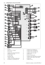
To do this, follow the wiring diagram in the appendix of
the installation instructions for the indoor unit.
7.7
Removing the cover for the electrical
connections
B
A
1.
Note that the cover contains a safety-relevant seal
which must be effective in the case of a leak in the
refrigerant circuit.
2.
Remove the cover, as shown in the figure, without
damaging the circumferential seal.


