background image

RDA 500-800 S

Ver.2 01.11.2002

31

3.7

Adjusting sowing depth

3.7.1

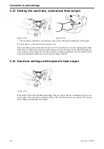
Adjusting the master and slave system

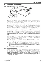
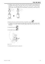
Figure 3.18 

The sowing depth of the drill is controlled by three hydraulic rams connected in series in a so-
called master and slave system. Before using the drill for the first time, the rams must be bled and 
their position zeroed in relation to each other thus:

Raise the drill to its topmost position so that all hydraulic rams are fully extended. Keep hold of 
the hydraulic lever in this position with the tractor engine running at half speed for 15-20 seconds. 
The rams have a transfer connection in the top position which means that oil can flow through the 
system and flush out any remaining air. Always repeat this bleed procedure for a few seconds after 
hitching on, before adjusting the drill, after unfolding and a few times during the working day.

After bleeding and zeroing the master and slave system, the sowing depth of the three sections can 
be set. This must be done with the drill in working mode out in the field. Check that the folding 
ram is fully extended and that the hydraulic pressure in the weight transfer system is normal, i.e. 
30-50 bar. Set the required working depth using the aluminium depth stop on the piston rod of the 
master ram which is located on the central section, see Position A. Drive forward and lower the 
drill. Keep holding the hydraulic lever for a few seconds, for example until the bout markers un-
fold.

Check the sowing depth at the centre of each section, see

 ”4.1 Sowing depth” on page 68.

 If nec-

essary, adjust the length of the piston rod on the relevant section. Normally, the rod of the master 
ram is kept around 10 mm unscrewed and the rod lengths of the slave rams, which are on the side 
sections, are adjusted instead. See Position B.

These adjustments must be made without removing any of the piston rod ends from the machine.

A

Loosen the opposing nut (C)

B

Turn the piston rod (B) with a spanner so that the rod end is screwed in or out. An outward 
adjustment gives a shallower sowing depth. 

NOTE!


The piston rods may be difficult to turn 

when the hydraulic rams are fully extended. Do not adjust the piston rod length beyond the dis-
tance.

C

Tighten the opposing nut (C) against the end of the rod (B).

3.7.2

Setting sowing depth

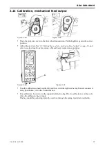
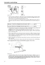
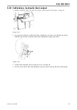
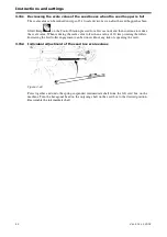
After the master and slave system has been adjusted, the sowing depth can be easily set by moving 
the depth stop (A) on the master ram. The scale does not show absolute sowing depths in centi-
metres but is only an index. After larger changes in sowing depth, the horizontal alignment of the 
drill may require adjustment, see

 ”3.6 Horizontal alignment” on page 30.

 Zero and bleed the sys-

tem for about 5 seconds as described above on several occasions during the working day. See also

”4.1 Sowing depth” on page 68.

Summary of Contents for RAPID RDA S Series

Page 1: ...Ver 2 01 11 2002 900225 en Instructions Seed drill RAPID series RDA 500 800 S No 12 000 12 799...

Page 2: ...2 Ver 2 01 11 2002...

Page 3: ...Peas Erbsen Pois 0 80 35 75 110 150 185 225 260 295 335 370 410 445 485 520 B nor Beans Bohnen F ves 0 85 35 75 110 145 185 220 255 290 330 365 400 440 475 510 Havre Oats Hafer Avoine 0 50 25 50 75 10...

Page 4: ...4...

Page 5: ...6 Fitting the following harrow 21 2 17 Fitting the pre emergence bout markers 22 2 18 Installation of lights 23 3 Instructions and settings 3 1 Tractor 24 3 2 Inspecting the drill s towing eyelet 24 3...

Page 6: ...Changing discs 80 5 10 Changing disc bearings 81 5 11 Changing seed coulter mounting bolts 82 5 12 Changing wheels 82 5 13 Changing the seals on the hydraulic rams 83 5 14 Changing the valve seals on...

Page 7: ...dures different to those mentioned in this manual The owner driver is solely responsible for using the drill correctly in every respect V derstad drills are subjected to thorough quality assurance ins...

Page 8: ...extension area of the drill is clear Never walk under a sus pended section Always check that the automatic catches have engaged before transport or parking To keep the automatic locks in perfect work...

Page 9: ...when the machine is not in the field The Con trol Box stores all values when switched off If the machine is parked and left resting only on the wheels and support leg the bout markers could start to s...

Page 10: ...rvice or repair work on the weight transfer hydraulic system the accumulators must be drained of oil See 5 15 Bleeding the hydraulic system accumulators on page 84 Be sure to set the master cylinder s...

Page 11: ...e 1 5 C Working width D Transport width E Serial CE number F For machines with mftg no 12000 12461 Weight empty incl following harrow and single Crossboard For more information see 7 5 Technical data...

Page 12: ...hains when lifting the drill When lifting with pallet forks lift from the front in the places indicated by the labels When lifting with lifting straps attach the straps to the folded up wings in the p...

Page 13: ...ntre section Install these rods on the correct seed box arms Discard of the elastic straps During installation of the centre section swivel rod slightly raise the related wheel on the drill while conn...

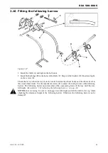
Page 14: ...e turnbuckle are unscrewed an equal distance Check that all bolts are properly tightened The horizontal alignment of the drill will be adjusted later see 3 6 Horizontal alignment on page 30 2 6 Fittin...

Page 15: ...he transport plates A While connecting the swivel rod to the seed box arm B the related wheel on the drill should be slightly raised For this purpose two people should help each other with the install...

Page 16: ...he lower mounting point of the fan to the special bracket C with a screw 3 Mount the radar D in the housing E Ensure that the joint F between the two plastic halves faces to the side Do not tighten th...

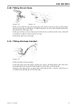
Page 17: ...well towards the centre of the drill so that there is sufficient room for the rate test bags Check all the other hose connections 2 11 Fitting the hose bracket Figure 2 12 Fit the hose clamp on the m...

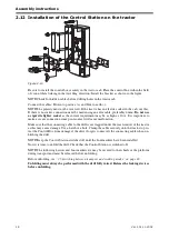
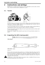
Page 18: ...It is important to make a secure connection since poor contact will cause malfunction Make sure that the connecting cable to the drill is not trapped under the rear window of the tractor as this may c...

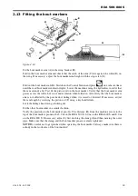
Page 19: ...under tension when folded in Also verify that the bout marker arm is not affected by the post harrow linkage when it is raised or lowered If necessary adjust the ram length by screwing the piston rod...

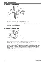
Page 20: ...vered with the scrapers folded up In such cases half of the fixing screws for the arm B are packed inside the hopper The distance between the scraper blade and the tyre should be at least 5 mm To chec...

Page 21: ...heel tracks and the others travel in the actual wheel tracks Use the adjustment screws F to adjust the work pressure of the following harrow The following harrow maintains almost the same spring force...

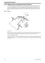
Page 22: ...ctor and then switch off the Control Station Do not walk on the wheels during installation since they could turn 2 17 1 Frame Figure 2 18 Install the front part of the frame B in the centre of the mid...

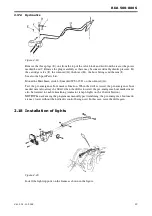
Page 23: ...tch J marked WS1 15 D on the solenoid G Test the pre emergence bout marker function When the drill is raised the pre emergence bout marker must also always be lifted when the drill is lowered the pre...

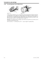
Page 24: ...rn inlet will be installed according to the tractor manufacture s instruction Female socket is delivered with the machine If the machine is equipped with a hydraulic top rod one more two way hydraulic...

Page 25: ...riving the drill with an intermediate packer Hitch the intermediate packer to the lifting arms of the tractor We recommend use of category 3 pins Adjust the lifting arms until the lateral travel of th...

Page 26: ...ssure hose to the hydraulic motor while the thinner is the oil leakage hose The thickest of the hoses the 3 4 return hose should be connected to a separate no pressure return entry Lock the female qui...

Page 27: ...pper larger holes in the hose brack et The hoses for raising should be put through the holes with the arrow pointing up and those for lowering through the holes with the arrow pointing down Figure 3 8...

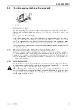
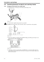
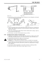
Page 28: ...on B Warning Do not stand with your feet under the tool bar as the machine can drop slightly Figure 3 10 C Raise the seed drill to its topmost position NOTE Folding and unfolding must always be car ri...

Page 29: ...t mode A Turn off the Low lift function on the Control Box Raise the drill to its topmost position NO TE Folding and unfolding must always be carried out with the central section fully raised B Fold t...

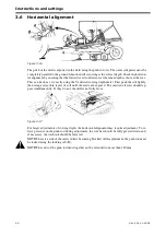
Page 30: ...ter First pack the soil lightly then scrape away thin layers of soil until the seeds are exposed The seeds in all rows should ap pear simultaneously If they do not the drill is not fully level Figure...

Page 31: ...he central section see Position A Drive forward and lower the drill Keep holding the hydraulic lever for a few seconds for example until the bout markers un fold Check the sowing depth at the centre o...

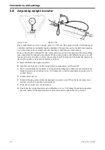
Page 32: ...justed The hydraulic pressure in the weight transfer system can be adjusted as follows A Raise the drill to the topmost position B Open the rear ball valve for the weight transfer accumulator see Posi...

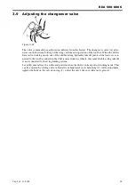
Page 33: ...de one of the double acting hydraulic takeoff points of the tractor is con nected to the tool bar and when the drill is raised onto its wheels this same double acting takeoff is now connected to the w...

Page 34: ...ched to the tractor fully unfolded resting on the seed coulters and on a firm surface If necessary adjust the piston rods A to obtain the same operating angle for all tool bars Loosen the opposing nut...

Page 35: ...The bracket has markings that show the basic settings for different draw bar heights 1 Draw bar height 300 400 mm 2 Draw bar height 400 600 mm 3 Draw bar height 600 800 mm Intermediate packer Prior t...

Page 36: ...roller a few turns and continue to reduce the scale setting When reducing the scale setting to values under 20 the roller should be rotated continuously The feed roller can be engaged increasingly wit...

Page 37: ...cale setting from the sowing table and based on previous experience Usually calibration is made on the left seed box with the right one having been disconnected using push button A on the Control Stat...

Page 38: ...ar a full scale test must be carried out Make 130 turns and weigh the seed collected x 2 The collected amount x 2 is the sowing rate of the drill If the amount collected weighs 3 kg the drill sowing r...

Page 39: ...re 3 35 2 Use the enclosed bags for calibration Prior to calibration reset the scale with the bags empty Push the bags into the seed boxes from below through the spring loaded doors Figure 3 36 3 Swit...

Page 40: ...3 38 8 Select a simulated driving speed to enable calibration to correspond to the actual sown amount 9 Fill up the output system by keeping the button above the button depressed for a few seconds Al...

Page 41: ...42 Also check to make sure that seed does not stick and build up on feed rollers and in the seed boxes Figure 3 41 12 Input the value in kg into the Control Station and confirm by pressing 13 A pulse...

Page 42: ...ontinue to reduce the scale value When reducing the scale value to less than a value of 20 keep rotating the rollers Increasing the feed roller engagement can be done without any risk of squeezing the...

Page 43: ...e there is nobody on the drill when feeding the seed Use of an extension handle on the knife blade is recommended Make sure there is nobody on the hopper Avoid contact with and inhalation of seed disi...

Page 44: ...all seed bags Filling should preferably be done using a loader and the bags placed on a pallet Lift the pallet diagonally from the front right with the tractor turned away to the side up to the guard...

Page 45: ...ive a distance L of 40 0 m with the RDA 500 S B 5 m a distance L of 33 3 m with the RDA 600 S B 6 m or a distance L of 25 0 m with the RDA 800 S B 8 m NOTE The fan and the other feed housing must be s...

Page 46: ...hydraulic system but no flow valve the fan speed is instead controlled with a check valve installed on the pressure line between the tractor and the sowing machine The check valve can be ordered as al...

Page 47: ...e coupling prop erly connects with the shaft 2 Install the top rod in the top rod mount of the tractor Please note the use of two mounting points 3 Install the hydraulic pump to the top rod Select the...

Page 48: ...ion should ideally be programmed to 300 rpm below the set rpm while the high rpm alarm should be set 300 rpm above the set rpm See 3 20 3 Program ming on page 57 NOTE During operation the oil temperat...

Page 49: ...mper has four positions Refer to the table below for recommended settings Sliding damper position 1 fully opened Small Grass seed The fourth or between third and fourth position depending on variety d...

Page 50: ...Instructions and settings 50 Ver 2 01 11 2002 3 20 Control station Figure 3 59 1 2 5 6 7 8 9 10 11 12 13 14 15 16 17 18 20 19 21 22 23 24 25 26 27 28 29 4 3 30 31 32 1...

Page 51: ...the button lights when automatic operation is engaged Manual change of bout marker 12 Information Used to explain alarm conditions to check the trip meter average speed etc 13 Enter 14 Escape 15 Sele...

Page 52: ...Instructions and settings 52 Ver 2 01 11 2002 Figure 3 60 1 2 5 6 7 8 9 10 11 12 13 14 15 16 17 18 20 19 21 22 23 24 25 26 27 28 29 4 3 30 31 32 1...

Page 53: ...n the display shows the speedometer the second one shows the area meter while the third row shows the fan rpm The fourth row shows the selected tramlining programme and the current sequence Alarms are...

Page 54: ...bout markers should be retracted without lifting the machine from the furrow e g to pass a post or well Press the button and lift the bout marker using the hy draulic lever Use to alternate between lo...

Page 55: ...the default value Max 5 steps and max up down of 99 Calibration only applies to hydraulic feed output Enter the calibration menu by simultaneously pressing and See Figure 3 61 Pro ceed according to 3...

Page 56: ...r ha speedometer average speed in km h and the total timer h It is not possible to reset the trip total area meter speedometer and the total timer The other meters can be reset by first selecting the...

Page 57: ...ackground Use to confirm a selection and then select or change the value of the selected item Confirm the value selection with Menus 1 Language Select the desired language for alarm texts etc 2 Machin...

Page 58: ...receipt of the alarm signal from the seed box rotation guards and the visual audible alarm of the Control Station The alarm should be slightly delayed to avoid alarms at low speeds Nevertheless the d...

Page 59: ...cre ated and or updated Also a short cut to the installation programme VaderstadControlSta tion will be created on the PC desktop 4 Double click on the VaderstadControlStation icon and follow the on...

Page 60: ...raised into place to close the outlet while opening a trap to allow seed to return to the hopper The flaps are controlled by a spring B on a motor driven disc C under the distributor head The electri...

Page 61: ...set using the Control Station The selected tramlining pro gramme is shown at the lower left of the display while the current furrow in the sequence is shown at the lower right part Keep the button de...

Page 62: ...mlining programme Start value Note 12 m 2 1 First bout drive with half the drill shut off Second bout overlap half the first bout 18 m 3 2 24 m 4 2 First bout drive with half the drill shut off Second...

Page 63: ...ft and the fore right one step inward Y For bigger changes in track width it may be necessary to move the hos es inside the hopper instead 3 21 2 Adjusting row shutoff Figure 3 67 Tramlining can be do...

Page 64: ...ll when turning Figure 3 69 3 Check that the following harrow tines trail in the between the wheel tracks and in the actual wheel tracks respectively This indicates that the following harrow tines tra...

Page 65: ...service Never work beneath the drill during service or maintenance without first ensuring that it is safely supported on stands and that all lifting rams are locked There are 3 lifting rams to contro...

Page 66: ...ers press the coulters closer to the discs as the nuts are tightened The nuts should not be tightened so much that the coulters cannot be rocked by hand It is important that the coulters do not press...

Page 67: ...ter fitting the lateral position of the scraper is not correct it can be adjusted using a suitable tool 3 27 Wing packers option Figure 3 76 The wing packer height can be set using the adjusting screw...

Page 68: ...seed lings On fields with varying soil type sowing depth should be checked and adjusted continually to en sure that the correct sowing depth is maintained throughout the field Sowing depth must be adj...

Page 69: ...re not sure whether the seed has blown out repeat this procedure Start with tramlining activated and with all coulters except those switched off for tramlining de livering seed Then advance past the t...

Page 70: ...e sowing or seed feed functions of the drill or any part thereof It is the responsibility of the operator to use properly pre treated seed treated with dressings which do not impair or prevent seed fe...

Page 71: ...t tramlining is to shut off Autostep be fore doing anything other than normal sowing or turning in headlands between bouts So remember to switch Autostep off before raising the drill to pass an obstru...

Page 72: ...rker again In this case it is not necessary use the functions selectors for auto advancing nor the bout markers 4 8 Turning with Low lift When the drill is lifted out of work at the headland the drive...

Page 73: ...RDA 500 800 S Ver 2 01 11 2002 73...

Page 74: ...e lifting rams during service on page 65 Ensure also that the surface supporting the trestles is firm enough to support them If the hopper is full which it ought not to be the weight of the drill is c...

Page 75: ...RDA 500 800 S Ver 2 01 11 2002 75 Figure 5 4...

Page 76: ...to be used for a long time Grease galvanized and chromium plated surfaces before long periods of storage To maintain the quality of this seed drill always use V derstad original spare parts 5 2 Seed f...

Page 77: ...rly Use grease on the angled surface of the locking bar and around where the bar is in contact with the hopper 5 5 Push rod push rod ram Figure 5 10 Dismantle the push rod at the end of the season and...

Page 78: ...A which controls the doors must be cleaned regularly Clean the hopper the rape brushes the feed housing and other components at the end of the sea son Check also that no seed has fallen into the eject...

Page 79: ...d indoors The Control Box should be stored at room temperature during the winter and between seasons Highly finished metal parts of the drill e g the piston rods and wearing surfaces should be greased...

Page 80: ...cate at the end of each season 5 9 Changing discs Make sure that the drill is securely supported on trestles When changing discs use a ratchet spanner or preferably a nut runner Turn the disc so that...

Page 81: ...an be ordered from V derstad Verken AB Part No 413549 When the bearings are changed the new seals must be greased See the diagram for details on the orientation of the seal components The bearing must...

Page 82: ...a few washers and a nut not a lock nut Grease the threads of the washers and nut well and draw the bolt in using the nut Be sure to use enough washers so that the nut does not go beyond the thread on...

Page 83: ...nscrew the piston rod guide A using the special key B B Pull out the piston rod and change the seals NOTE Be very sure that the seals are facing the correct way C Carefully check that the collar C is...

Page 84: ...lve is probably leaking 5 15 Bleeding the hydraulic system accumulators NOTE Before starting service work on the part of the hydraulic system controlling the folding and weight transfer system drain a...

Page 85: ...apy water on the hoses when removing and refitting Twist the hose anticlockwise during removal and replacement so that the spiral reinforcement opens up the hose slightly Cut the spare hose to the sam...

Page 86: ...d pull the motor slightly forward until the chain deflection is correct 5 20 Replacing the oil filter in the hydraulic unit Cleanliness is imperative when servicing and performing maintenance on the h...

Page 87: ...ighten by hand In order to bleed the system and to clean the filled up oil as well operate the fan while keeping the tractor at idle for a couple of minutes see below 5 21 2 Oil and oil filter replace...

Page 88: ...ince it could cause damage to the pump and pump motor Start the fan with the tractor at idle Listen to the fan and wait until it operates smoothly If air bubbles are visible in the inspection window a...

Page 89: ...wn and ground blue been connected properly Check whether the automatic fuse of the Control Station has tripped Check the settings on the Control Station Check whether both connectors of the intermedia...

Page 90: ...etism may be present in the nut perform this inspection with the power switched on and off The bout marker valves A and B receive current when their indicator lamps on the Control Station light and th...

Page 91: ...agnet See the figure This can easily be tested using a multimeter and a magnet 6 1 5 Inductive detector Figure 6 4 These sensors trigger when metal objects pass within a distance of 1 1 5 mm A functio...

Page 92: ...out marker valves when the wings of the drill are retracted This prevents a bout marker from being unintentionally unfolded in this position Disconnect to the switch connector from the Workstation and...

Page 93: ...rker ram does not leak on the outside and inside For seal replacement see 5 13 Changing the seals on the hydraulic rams on page 83 If the bout marker unfolds when the machine is parked set the stopper...

Page 94: ...off the Control Station and check whether the drill can be raised If it is still not possible to raise the machine the fault can be found in the hydraulic sys tem Check whether a shortcircuit has occ...

Page 95: ...r and remove the quick connector Start the fan Collect the drained oil in a container Measure the pressure Measure the amount of oil ex iting during one full minute A considerable pressure drop would...

Page 96: ...and inspect the sensor See 6 1 5 Inductive de tector on page 91 Check the cable connector and connection of the sen sor Has the correct drive wheel circumference been pro grammed into the Control Stat...

Page 97: ...discs afford better traction if the seed boxes are raised one notch Are discs excessively worn Does the soil surface contain a lot of plant scrubs Are the tines of the front implement set too hard re...

Page 98: ...he LED of the sensor should light when the toothed plate passes The distance between the sensor and the toothed plate should be 1 2 mm Adjust if necessary A lit LED however is not necessarily any guar...

Page 99: ...he sensor If the alarm is generated intermittently a likely cause is incorrect adjustment of the sensor or a defective sensor 19 Seed fan high rpm Check whether the hydraulic oil flow from the tractor...

Page 100: ...onnectors The green indicator lamp on the Workstation shows that voltage is present however the lamp could light even though the intermediate cable is partially damaged 29 Voltage error Workstation 1...

Page 101: ...the hydraulic oil flow sufficient Does the seed out put fan start Check whether the seed boxes can rotate by hand Check the cable connector and connection of the sen sor Check the operation of the sen...

Page 102: ...able Always perform seed calibration The information in the sowing table should be used only as a guideline For small seed output amounts new seed calibrations should be performed regu larly Check the...

Page 103: ...415 450 485 rtor Peas Erbsen Pois 0 80 35 75 110 150 185 225 260 295 335 370 410 445 485 520 B nor Beans Bohnen F ves 0 85 35 75 110 145 185 220 255 290 330 365 400 440 475 510 Havre Oats Hafer Avoine...

Page 104: ...Appendices 104 Ver 2 01 11 2002 7 2 Calibration Results Table 7 1 Crop kg dm High low gear Scale reading 10 20 30 40 50 60 70 80 90 100 110 120 130 140...

Page 105: ...RDA 500 800 S Ver 2 01 11 2002 105...

Page 106: ...Appendices 106 Ver 2 01 11 2002 7 3 Hydraulic diagram 7 3 1 Hydraulic diagram RDA 500 600 S Figure 7 1 428717...

Page 107: ...Hydraulic ram folding and weight transfer 12 Valve block Lift stop bout markers pre emergence markers 13 2 way valve drive wheel sensing Only on RDA 500 S 14 3 way ball valve transport position 15 2 w...

Page 108: ...Appendices 108 Ver 2 01 11 2002 7 3 2 Hydraulic diagram RDA 800 S Figure 7 2 428718...

Page 109: ...raulic ram folding and weight transfer 12 Valve block Lift stop bout markers pre emergence markers 13 Flow divider folding 14 3 way ball valve transport position 15 2 way valve transport position 16 2...

Page 110: ...Appendices 110 Ver 2 01 11 2002 7 3 3 Fenix fl kt standard Figure 7 3 A Hydraulic motor B Valve block C Tractor B A C...

Page 111: ...S Ver 2 01 11 2002 111 7 3 4 Fenix fan PTO Figure 7 4 A Hydraulic pump B Hydraulic motor C Choke valve D Radiator E Air filter F Oil filter G Contamination indicator H Hydraulic tank I Tractor A B C...

Page 112: ...112 Ver 2 01 11 2002 7 3 5 Hydraulic feed output Figur 7 5 429874 A Fan B Seed box C Hydraulic motors D Oil filter E 3 port pressure compensating flow valve F Damping valve G 2 way cock H Tractor A B...

Page 113: ...ft hand seed output roller WS1 5 Fan revolution counter WS1 6 Speedometer drive wheel radar WS1 8 Mini remote WS1 9 Wing folding boundary switch WS1 10 Low lift switch WS1 12 Check valve output motor...

Page 114: ...cted Matter not detected WS1 1 WS1 2 1 Black 1 Matter detected Soil LED lights Max 1 V Min 8 V 2 White 2 Matter not detected Soil Min 8 V Max 1 V 3 Brown 3 12 V 4 Blue 4 0 V Tabell 7 4 Workstation con...

Page 115: ...Tabell 7 5 Workstation connection Terminal A Cable colour Terminal B Function WS1 16 WS1 17 1 Black 1 Tramlining off 12 V 2 Brown 2 Tramlining on 12 V 3 3 4 Blue 4 0 V Tabell 7 6 Workstation connecti...

Page 116: ...ell 7 7 Workstation connection Terminal A Cable colour Terminal B Function WS1 12 WS1 14 WS1 15 WS1 18 WS1 19 WS1 20 WS1 21 1 2 Brown 1 12 V supply to valve red lamp lights 3 4 Blue 2 0 V Tabell 7 8 W...

Page 117: ...2 7 4 9 Terminator plug Figur 7 13 Tabell 7 9 Pole Cable colour Function 1 Blue 0 V 2 Yellow CAN LO communication 3 Brown 12 V Green CAN HI communication Tabell 7 10 Pole Function 1 0 V 2 Terminator r...

Page 118: ...7 4 11 Radar Figure 7 15 Tabell 7 11 Pole Cable colour Function 1 Green 360 pulses per turn pulse ground signal 2 Red 12 V 3 Black 0 V Tabell 7 12 Workstation connection Pole A Cable colour Pole B Fu...

Page 119: ...WS1 8 1 Black Seed output by depressing push button B contact between terminal 1 and terminal 4 on WS1 8 4 Blue 0 V Table 7 14 Workstation connection Pole Cable colour Function WS1 23 1 Brown Seed ou...

Page 120: ...600 S RDA 800 S Working width m 5 0 6 0 8 0 Transport width m 3 0 3 0 3 0 Transport height m 3 4 3 4 4 0 Transport height with advantage collar m 3 5 3 6 4 0 Filling height m 2 8 2 8 3 0 Filling heig...

Page 121: ......
Page 122: ...590 21 V DERSTAD S 590 21 V DERSTAD SWEDEN Telefon 0142 820 00 Telephone 46 142 820 00 Telefax 0142 820 10 Telefax 46 142 820 10 www vaderstad com...

Reviews: