vacon • 14
Filter types
Local contacts: https://www.danfoss.com/en/contact-us/contacts-list/
2.2
dU/dt filters
2.2.1
General
The VACON
®
NX drives use IGBT transistors as an output element. These semiconductors create
the correct voltage to the motor switching it at very high speed (4 - 6 kV/s) with an unloaded IGBT.
This high speed will, under certain circumstances, cause extra voltage stress on the main insulation
of the motor.
Usually there are no problems with motors designed for a 400 V supply. Such motors are usually
designed for a voltage level of 1200 V, which exceeds the AC drive induced stress.
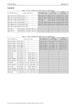
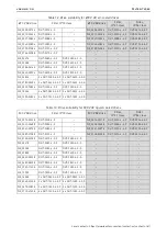
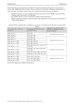
In 500 V supplies the motor has to withstand at least 1600 V. A dU/dt filter is often required with
these motors in order not to exceed the allowable voltage stress. In 690 V supplies the motor has to
withstand at least 1800 V, and a dU/dt filter is required in these cases.
NOTE!
In uncertain cases, confirm the rating of the motor in AC drive application with the motor
manufacturer.
NOTE!
Set the switching frequency parameter to correspond to the value printed on the nameplate
of the filter and the output voltage level. Do not increase the switching frequency above the rated
value of the filter. Decreasing it below is allowed.
The high switching speed (about 2 kV/s) with the motor and cable connected, creates a travelling
wave in the cable. The speed of this wave is set by the cable's wave impedance, usually about 50 -
100 Ω. This is less than the motor's wave impedance, which is on the order of 1 kΩ. As the travelling
voltage wave hits this discontinuity, it is reflected back, increasing the instantaneous voltage on the
motor winding. The wave is reflected back and forth between motor and drive and finally the steady
state voltage is reached.
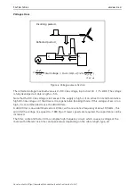
Winding voltage stresses
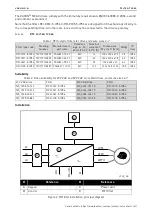
The rapid change in voltage is not distributed equally over all windings, but the first windings show
higher voltage stresses than the inner ones, due to the capacitive coupling between the windings.
Modern motors can withstand a voltage rise times of < 2 kV/µs. In case of doubt, use a dU/dt filter
or contact the motor manufacturer.
Figure 5. Change of the voltage shape in winding
#
Reference
#
Reference
A
Incoming pulse
B
Winding voltage
B
A
7122_00


