


vacon • 150
Parameters
Local contacts: https://www.danfoss.com/en/contact-us/contacts-list/
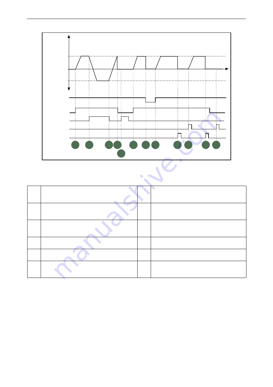
Figure 45. I/O A Start logic = 1
7.2.4
References
P3.3.1.1 M
IN
F
REQ
R
EFERENCE
Minimum frequency reference.
NOTE:
When drive is fed by solar power, if available power is not sufficient to maintain dc voltage
above the minimum and frequency above the minimum, the drive will be stopped.
NOTE
: if motor current limit is reached, actual output frequency might be lower than this parame-
ter. If this is not acceptable, stall protection should be activated.
Table 138.
1
Control signal (CS) 1 activates causing the output
frequency to rise. The motor runs forward.
7
Run enable signal is set to FALSE, which drops the
frequency to 0. The run enable signal is configured
with parameter P3.5.1.15.
2
CS2 activates which causes the direction to start
changing (FWD to REV).
8
Run enable signal is set to TRUE, which causes the
frequency to rise towards the set frequency
because CS1 is still active.
3
CS2 is inactivated which causes the direction to
start changing (REV to FWD) because CS1 is still
active.
9
Keypad stop button is pressed and the frequency
fed to the motor drops to 0. (This signal only works
if P3.2.3 Keypad stop button = Yes)
4
Also CS1 inactivates and the frequency drops to 0.
10
The drive starts through pushing the Start button
on the keypad.
5
Despite the activation of CS2, the motor does not
start because CS1 is inactive.
11
The drive is stopped again with the stop button on
the keypad.
6
CS1 activates causing the output frequency to rise
again. The motor runs forward because CS2 is inac-
tive.
12
The attempt to start the drive through pushing the
Start button is not successful because CS1 is inac-
tive.
t
Output
frequency
FWD
REV
Ctrl signal 2
Ctrl signal 1
Run enable
Set frequency
Set frequency
0 Hz
Keypad stop
button
Keypad start
button
1
2
3
4
6
7
8
9
10
11
12
9142.emf
5


