background image

16 


seconds. 

The icons of 

 and 


and the 

warning code


  flash on LCD 

display. Alarm is sounding every 2 

seconds. 

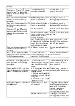
The internal battery is 

incorrectly connected. 

Confirm batteries are 

properly connected 

Fault code 27 is displayed on the LCD 
and the alarm is continuously 
sounding. 

Battery voltage is too high or 
there’s a charger fault. 

Contact your reseller or 
[email protected] 

Fault code 28 is displayed on the LCD 

and the alarm is continuously 
sounding. 

Battery voltage is too low or 

there’s a charger fault. 

Contact your reseller or 

[email protected] 

The icons 

 and 

 and the 

warning code


flash on LCD 

display. Alarm is sounding every 
second. 

UPS is overloaded  

Remove  excess  loads  from 
the UPS. 

UPS is overloaded. Devices 
connected to the UPS are fed 
directly by the electrical 
network via Bypass. 

Remove  excess  loads  from 
the UPS. 

After repeat overloads, the 
UPS is locked in the Bypass 
mode. Connected devices 
are fed directly by mains. 

First, remove excess loads 
from UPS. Then shut down 
the UPS and restart it. 

Fault code 49 is displayed on the LCD 
and the alarm is continuously 
sounding. 

UPS is over input current. 

Remove excess loads from 
UPS. 

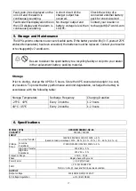
Fault code 43 and the icon 

 is 

displayed on the LCD and the alarm 
is continuously sounding. 

The UPS shuts down 

automatically because of an 
overload of the UPS output. 

Remove excess loads from 

UPS and restart it. 


Fault code 14 is displayed on the 
LCD and alarm is continuously 

sounding. 

The UPS shuts down 
automatically because of a 

short circuit on the UPS 
output. 

Check output wiring and if 
connected devices have 

short circuited 

Fault code 01, 02, 03, 11, 12, 13 or 
41


is displayed on the LCD and the 

alarm is continuously sounding. 

A  UPS  internal  fault  has 
occurred.  There  are  two 

possible results: 
1. The load is still supplied, 
but directly from AC power 

via bypass.  
2.  The  load  is  no  longer 
supplied by power.  

Contact  your  reseller  or 
[email protected] 

Battery backup time is shorter than 

nominal value. 

Batteries have not been 

fully charged 

Charge the batteries for at 

least 5 hours and then check 
capacity. If the problem 
persists, consult your 

reseller or contact 
[email protected] 

Possible batteries defect 

Contact your reseller or 
[email protected] 

Summary of Contents for UPS2URM3000DC-NC-1E

Page 1: ...UPS 3000VA SINGLE PHASE DOUBLE CONVERSION ONLINE 2U R T LCD USERS MANUAL UPS2URM3000DC NC 1E...

Page 2: ...protection 5 USB communication port 6 RS 232 communication port 7 SNMP intelligent port 8 Emergency power off function connector EPO 9 External battery connection not supported 1 2 Operation The UPS...

Page 3: ...ory without connecting battery wires Before installation of the UPS please follow the steps below to re connect the battery wires Rack Mount Installation Caution DO NOT use the mounting brackets to li...

Page 4: ...of 3000m for normal operation at full load 2 UPS input connection Plug the UPS into a two pole three wire grounded receptacle only Avoid using extension cords For 200 208 220 230 240VAC models The pow...

Page 5: ...r to the communication port of your PC With the monitoring software installed you can schedule UPS shutdown start up and monitor UPS status through PC The UPS is equipped with an SNMP Network card Whe...

Page 6: ...on screen instructions to install the software 1 5 Battery Replacement Note This UPS is equipped with internal batteries and only a trained technician should replace the batteries Replace the batteri...

Page 7: ...arm After the UPS is turned on and in battery mode press and hold this button for at least 3 seconds to disable or enable the alarm system N A for warnings or errors Up key Press this button to displa...

Page 8: ...enu In setting mode press the ON Mute and Select buttons simultaneously for 0 2 seconds to return to the upper menu Once in the main menu exit settings mode by pressing these two buttons simultaneousl...

Page 9: ...C circuit is working Indicates the PFC circuit is working Indicates the inverter circuit is working Indicates the UPS is working in converter mode Indicates the output is working Battery information I...

Page 10: ...Replace EE EEPROM error 3 5 UPS Setting Parameter 1 Parameter 2 There are two parameters to set up the UPS Parameter 1 Program alternatives Refer to below table Parameter 2 Setting options or values...

Page 11: ...y is 60Hz 04 ECO enable disable Interface Setting Parameter 2 Enable or disable ECO function ENA ECO mode enable DIS ECO mode disable Default 05 ECO voltage range setting Interface Setting Parameter 2...

Page 12: ...g Parameter 2 Set the acceptable high frequency point and acceptable low frequency point for Bypass mode by pressing the Down key or Up key HLS Bypass high frequency point For 50Hz output frequency mo...

Page 13: ...ing Parameter 2 Set the battery total AH of the UPS 7 999 Setting the battery total capacity from 7 999 in AH Please set the correct battery total capacity if external battery bank is connected 13 Max...

Page 14: ...fault detection enable Default DIS Site fault detection disable 18 Display setting for autonomy time Interface Setting Parameter 2 Set the display setting for autonomy time EAT If EAT is selected it...

Page 15: ...When the input voltage is beyond the acceptable range or in power failure the UPS provides power from battery and the alarm will sound every 5 seconds Bypass mode When input voltage is within acceptab...

Page 16: ...very 2 seconds EEPROM error Sounds every 2 seconds Note Site Wiring Fault function can be enabled disabled via software Please check software manual for the details 4 Troubleshooting If the UPS system...

Page 17: ...it Faultcode49isdisplayedontheLCD and the alarm is continuously sounding UPS is over input current Remove excess loads from UPS Fault code 43 and the icon is displayed on the LCD and the alarm is con...

Page 18: ...upright in a cool dry location To protect battery performance and limit degradation recharge the battery in accordance with the following table Storage Temperature Recharge Frequency Charging Duratio...

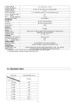
Page 19: ...ustable Charging Voltage 82 1 VDC 1 PHYSICAL Dimension D X W X H mm 630 x 438 x 88 Net Weight kgs With battery 27 5 Without battery 12 4 ENVIRONMENT Operation Humidity 20 95 RH 0 40 C non condensing N...

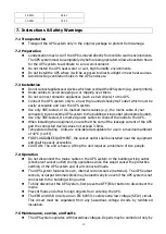
Page 20: ...les to connect the loads to the UPS When installing the equipment ensure that the sum of the leakage current of the UPS and the connected devices does not exceed 3 5mA Temperature Rating Units are con...

Page 21: ...voltage Hazardous voltages may occur between the battery terminals and the ground Before touching verify that no voltage is present Caution Do not dispose of batteries in a fire The batteries may expl...

Page 22: ...UPS 3000VA EINPHASIG IM DAUERBETRIEB NACH DOPPELWANDLER PRINZIP 2U R T LCD BENUTZERHANDBUCH UPS2URM3000DC NC 1E...

Page 23: ...sschutz f r Netzwerk Fax Modem 5 USB Kommunikationsport 6 RS 232 Kommunikationsport 7 Intelligenter SNMP Anschluss 8 Anschluss f r Notabschaltungsfunktion EPO 9 Externer Akkuanschluss nicht unterst tz...

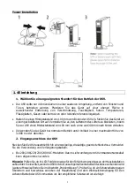
Page 24: ...verbunden sind Vor der Installation der USV f hren Sie bitte die nachstehenden Schritte zur erneuten Verbindung der Akku Anschlusskabel durch Installation im Gestellrahmen Vorsicht Verwenden Sie die H...

Page 25: ...300 mm nach hinten einhalten Verwenden Sie das Ger t bei normalem Betrieb unter Volllast in einer maximalen H he von 3 000 m oder darunter 2 Eingangsanschluss der USV Stecken Sie die USV ausschlie lic...

Page 26: ...inden Sie ein Ende des Kommunikationskabels mit dem USB RS 232 Port und das andere Ende mit dem Kommunikationsport Ihres PC Mit der installierten berwachungssoftware k nnen Sie das Herunterfahren den...

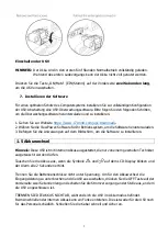
Page 27: ...tware herunterzuladen 3 Befolgen Sie die Anweisungen auf dem Bildschirm um die Software zu installieren 1 5 Akkuwechsel Hinweis Diese USV ist mit internen Akkus ausgestattet die nur von einem geschult...

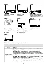
Page 28: ...der am Ger t an 2 1 Tastenfunktionen Taste Funktion ON Mute Taste AN Stumm Taste Einschalten der USV Halten Sie die ON Mute Taste zwei Sekunden lang gedr ckt um die USV einzuschalten Stummschalten des...

Page 29: ...Dr cken Sie diese Taste um die n chste Auswahl im USV Einstellmodus anzuzeigen ON Mute Select Taste Wechsel zum Bypass Modus Wenn die Hauptstromversorgung normal ist dr cken Sie die Tasten ON Mute un...

Page 30: ...mationen zum Modusbetrieb Gibt an dass die USV mit dem Netz verbunden ist Gibt an dass der Akku funktioniert Gibt den Ladestatus an Gibt an dass der Bypass Stromkreis funktioniert Gibt an dass der ECO...

Page 31: ...Aktiv Schlie en EAT Gesch tzte berbr ckungszeit RAT Laufende berbr ckungszeit SD Herunterfahren OK OK ON ON BL Akkustand niedrig OL berlastung OI ber Eingangsstrom NC Akku nicht verbunden OC berladun...

Page 32: ...lung 240 gibt an dass die Ausgangsspannung 240 Vac ist 02 Aktivieren Deaktivieren des Frequenzkonverters Schnittstelle Einstellung Parameter 2 Konvertermodus aktivieren oder deaktivieren CF ENA Konver...

Page 33: ...stellung Parameter 2 Legen Sie die zul ssige Mindest und Maximalspannung f r den Bypass Modus fest indem Sie auf die Nach unten Taste oder Nach oben Taste dr cken HLS Bypass Hochspannungspunkt Bei 200...

Page 34: ...999 Einstellen der Reservezeitgrenzwerte in Minuten von 0 999 bei programmierbaren Ausg ngen die im Akkumodus mit nicht kritischen Ger ten verbunden sind Standardeinstellung 999 11 Einstellen der berb...

Page 35: ...Zelle 15 Einstellen der Erhaltungsspannung f r das Ladeger t Schnittstelle Einstellung Parameter 2 Einstellen der Erhaltungs spannung f r das Ladeger t 2 20 2 33 Einstellen der Anhebungsspannung f r...

Page 36: ...rigspannungspunkt Bei 200 208 220 230 240 VAC Modellen 110 120 130 140 150 160 Einstellen des Niedrigspannungspunktes in Parameter 2 Standardeinstellung 110 Vac 00 Exit Einstellung Schnittstelle Einst...

Page 37: ...r Code Symbol Fehlerereignis Fehler Code Symbol BUS Start fehlgeschlagen 01 x Akkuspannung zu hoch 27 x BUS dar ber 02 x Akkuspannung zu niedrig 28 x BUS darunter 03 x Ausgang Ladeger t kurz 2 A x Inv...

Page 38: ...kunden Die Netz und Nullleiter des USV Eingangs sind vertauscht Drehen Sie den Hauptstromeingang um 180 und verbinden Sie ihn dann mit dem USV System Die Symbole und sowie der Warncode blinken im LCD...

Page 39: ...er des Akku Backups ist k rzer als der Nennwert Die Akkus wurden nicht vollst ndig aufgeladen Laden Sie die Akkus mindestens 5 Stunden und pr fen Sie dann die Kapazit t Wenn das Problem weiterhin best...

Page 40: ...zbereich Synchronisierter Bereich 47 53 Hz oder 57 63 Hz Frequenzbereich 50 Hz 0 1 Hz oder 60 Hz 0 1 Hz Akkumodus Stromscheitelfaktor 3 1 Harmonische Verzerrung 2 THD Lineare Last 4 THD Nicht lineare...

Page 41: ...blockiert werden 7 3 Installation Schlie enSiekeineGer tean diedasUSV System berlastenk nnen z B Laserdrucker F hren Sie die Kabel so dass Sie nicht darauf treten oder dar ber stolpern Schlie en Sie...

Page 42: ...annung an den Anschl ssen von Hochleistungsger ten wie BUS Kondensatoren mehr vorhanden ist Um einen Stromschlag zu vermeiden schalten Sie das Ger t aus und trennen Sie es vom Stromnetz bevor Sie den...

Page 43: ...MANUAL DE USUARIO DE SAI 3000 VA TORRE RACK EN 2U ONLINE MONOF SICO DE DOBLE CONVERSI N UPS2URM3000DC NC 1E...

Page 44: ...5 Puerto de comunicaciones USB 6 Puerto de comunicaciones RS 232 7 Puerto inteligente SNMP 8 Conector de la funci n de apagado de emergencia EPO 9 Conexi n de la bater a externa no compatible 1 2 Func...

Page 45: ...desconectados Antes de instalar el SAI siga los pasos que se indican a continuaci n para volver a conectar los cables de la bater a Instalaci n en bastidor Precauci n NO utilice los soportes de monta...

Page 46: ...ee Util celo a una altitud igual o inferior a 3000 m para un funcionamiento normal a plena carga 2 Conexi n de la entrada del SAI Conecte el SAI nicamente a tomas conectadas a tierra de dos polos para...

Page 47: ...xtremo del cable de comunicaciones al puerto USB RS 232 y el otro extremo al puerto de comunicaciones de su PC Si tiene el software de supervisi n instalado puede programar el apagado encendido del SA...

Page 48: ...para su sistema operativo para descargarlo 3 Siga las instrucciones en pantalla para instalar el software 1 5 Sustituci n de las bater as Nota este SAI est equipado con bater as internas y solo un t...

Page 49: ...o en la unidad 2 1 Funcionamiento de los botones Bot n Funci n Bot n ON Mute Encender el SAI mantenga pulsado el bot n ON Mute durante 2 segundos como m nimo para encender el SAI Silenciar la alarma t...

Page 50: ...modo de bypass Tecla de bajada pulse este bot n para mostrar la siguiente selecci n en el modo de ajustes del SAI Botones ON Mute Select Cambiar al modo de bypass cuando el suministro el ctrico sea n...

Page 51: ...est n funcionando Informaci n sobre el modo de funcionamiento Indica que el SAI est conectado al suministro el ctrico Indica que la bater a est funcionando Indica el estado de carga Indica que el cir...

Page 52: ...de autonom a estimado RAT Tiempo de autonom a de ejecuci n SD Apagado OK Aceptar ON Encendido BL Bater a baja OL Sobrecarga OI Sobrecorriente de entrada NC Bater a no conectada OC Sobrecarga SF Fallo...

Page 53: ...de salida es 240 VCA 02 activaci n desactivaci n del transformador de frecuencia Interfaz Ajuste Par metro 2 active o desactive el modo de transformador CF ENA activaci n del modo de transformador CF...

Page 54: ...para establecer el punto de alta tensi n y el punto de baja tensi n aceptables en el modo de bypass pulse la tecla de bajada o la tecla de subida HLS punto de alta tensi n de bypass En los modelos de...

Page 55: ...tiempode respaldoen minutos de 0 a999 para salidas programables que se conectan a dispositivos no cr ticos en modo de bater a ajuste predeterminado 999 11 ajuste de la limitaci n de autonom a Interfaz...

Page 56: ...15 ajuste de la tensi n de flotaci n del cargador Interfaz Ajuste Par metro 2 ajuste la tensi n de flotaci n del cargador 2 20 2 33 ajuste la tensi n de flotaci n del cargador de 2 20 V celda a 2 33 V...

Page 57: ...aja tensi n de bypass En los modelos de 200 208 220 230 240 VCA 110 120 130 140 150 160 ajuste del punto de baja tensi n del par metro 2 ajuste predeterminado 110 VCA 00 salida de los ajustes Interfaz...

Page 58: ...allos Fallo C digo de fallo Icono Fallo C digo de fallo Icono Fallo del inicio del bus 01 x Tensi n de la bater a demasiado alta 27 x Exceso de bus 02 x Tensi n de la bater a demasiado baja 28 x Defec...

Page 59: ...Los iconos y y el c digo de advertencia parpadean en lapantallaLCD Laalarmasuena cada 2 segundos Los conductores de l nea y de neutro de la entrada del SAI est n invertidos Gire la toma de alimentaci...

Page 60: ...o un fallo interno del SAI Hay dos resultados posibles 1 La carga sigue funcionando pero directamente desde el suministro de CA mediante el bypass 2 La carga ya no recibe suministro P ngase en contact...

Page 61: ...porcentaje de carga que puede ser 100 80 80 70 70 60 o 60 0 Retorno de l nea baja 175 VCA 155 VCA 135 VCA 125 VCA 5 Transferencia de l nea alta 300 VCA 5 Retorno de l nea alta 290 VCA 5 Intervalo de f...

Page 62: ...72 53 7 Instrucciones y advertencias de seguridad 7 1 Transporte Transporte el SAI solo en su embalaje original para protegerlo de da os 7 2 Preparaci n Puede producirse condensaci n si el SAI se muev...

Page 63: ...e encuentran dentro del SAI siguen conectados a la bater a conducen electricidad y son peligrosos Antes de realizar cualquier tarea de reparaci n o mantenimiento desconecte las bater as y confirme que...

Page 64: ...MANUEL D UTILISATION DE L ONDULEUR EN LIGNE MONOPHAS DOUBLE CONVERSION 3000 VA 2U MONTAGE EN RACK TOUR CRAN LCD UPS2URM3000DC NC 1E...

Page 65: ...ort de communication USB 6 Port de communication RS 232 7 Port intelligent SNMP 8 Connecteur de fonction d arr t d urgence EPO 9 Connexion une batterie externe non prise en charge 1 2 Fonctionnement L...

Page 66: ...a batterie soient branch s Avant l installation de l onduleur veuillez suivre les tapes suivantes pour reconnecter les c bles de la batterie Installation en rack Avertissement NE PAS utiliser les supp...

Page 67: ...mm derri re l onduleur Utilisez le unealtitude galeouinf rieure 3 000 mpourunfonctionnementnormal pleinecharge 2 Connexion d entr e de l onduleur Branchez l onduleur dans une prise bipolaire trifilai...

Page 68: ...surveillance connectez une extr mit du c ble de communication au port USB RS 232 et l autre extr mit au port de communication de votre PC Avec le logiciel de surveillance install vous pouvez programme...

Page 69: ...d exploitation pour t l charger le logiciel 3 Suivez les instructions affich es l cran pour installer le logiciel 1 5 Remplacement de la batterie Remarque cet onduleur est quip de batteries internes...

Page 70: ...des boutons Bouton Fonction Bouton ON Mute Marche Muet Mise sous tension de l onduleur appuyez sur le bouton ON Mute Marche Muet pendant au moins 2 secondes pour mettre l onduleur sous tension D sact...

Page 71: ...s appuyez sur ce bouton pour afficher la s lection suivante en mode de r glage de l onduleur Bouton ON Mute Marche Muet Select S lection Passage en mode de d rivation lorsque l alimentation principale...

Page 72: ...rises de gestion programmables fonctionnent Informations sur le mode de fonctionnement Indique que l onduleur se connecte au secteur Indique que la batterie fonctionne Indique l tat de chargement Indi...

Page 73: ...utonomie estim e RAT Dur e d autonomie en fonctionnement SD Arr t OK OK Marche Marche BL Batterie faible OL Surcharge OI Surcharge de courant d entr e NC Batterie non connect e OC Surcharge SF D faill...

Page 74: ...t 240 la tension de sortie actuelle est de 240 Vca 02 Activation d sactivation du convertisseur de fr quence Interface R glage Param tre 2 activation d sactivation du mode convertisseur CF ENA activat...

Page 75: ...de d rivation Interface R glage Param tre 2 r glez le point de haute tension et le point de basse tension acceptables pour le mode de d rivation en appuyant sur la touche Down Bas ou la touche Up Haut...

Page 76: ...dur e de sauvegarde en minutes de 0 999 pour les prises programmables qui se connectent des appareils non critiques en mode batterie Par d faut 999 11 R glage de limitation de l autonomie Interface R...

Page 77: ...de la tension de flottement du chargeur Interface R glage Param tre 2 r glage de la tension de flottement du chargeur 2 20 2 33 r glage de la tension de flottement du chargeur de 2 20 V cellule 2 33...

Page 78: ...mod les 200 208 220 230 240 VCA 110 120 130 140 150 160 r glage du point de basse tension dans le param tre 2 Par d faut 110 Vca 00 Param tre de sortie Interface R glage Quitter le mode de r glage 3...

Page 79: ...d faillance Ic ne v nement de d faillance Code de d faillance Ic ne chec du d marrage du bus 01 x Tension de la batterie trop lev e 27 x Surcharge du bus 02 x Tension de la batterie trop faible 28 x...

Page 80: ...ondes La fonction EPO est activ e Mettez le circuit en position ferm e pour d sactiver la fonction EPO Les ic nes et et le code d avertissement clignotent sur l cran LCD L alarme retentit toutes les 2...

Page 81: ...ion AC au moyen d une d rivation 2 La charge n est plus aliment e par le courant Contactezvotrerevendeurou techsupport v7 world com La dur e de sauvegarde de la batterie est plus courte que la valeur...

Page 82: ...Port e de fr quence 50 Hz 0 1 Hz ou 60 Hz 0 1 Hz mode batterie Facteur de cr te actuel 3 1 Distorsion harmonique THD de 2 charge lin aire THD de 4 charge non lin aire Dur e du transfert Mode AC vers l...

Page 83: ...d appareils qui peuvent surcharger le syst me de l onduleur p ex imprimantes laser Acheminez les c bles de mani re viter de marcher ou de tr bucher dessus Ne connectez pas d appareils m nagers p ex s...

Page 84: ...une tension dangereuse aux terminaux des condensateurs haute capacit tels que les condensateurs BUS Afin d viter tout choc lectrique teignez les unit s et d branchez le de la source d alimentation AC...

Page 85: ...UPS 3000VA MONOFASE DOPPIA CONVERSIONE ONLINE MANUALE UTENTE LCD 2U R T UPS2URM3000DC NC 1E...

Page 86: ...tensione per rete fax modem 5 Porta di comunicazione USB 6 Porta di comunicazione RS 232 7 Porta intelligente SNMP 8 Connettore per funzione EPO Emergency Power Off 9 Connessione batteria esterna non...

Page 87: ...batteria scollegati Prima di installare l UPS attenersi alla procedura seguente per ricollegare i cavi della batteria Installazione con montaggio a rack ATTENZIONE NON utilizzare le staffe di montagg...

Page 88: ...0 mm sulla parte posteriore dell UPS Utilizzare ad un altitudine massima di 3 000 m per un funzionamento normale a pieno carico 2 Collegamento dell ingresso dell UPS Collegare l UPS solo a una presa c...

Page 89: ...llegare un estremit del cavo di comunicazione alla porta USB RS 232 e l altra alla porta di comunicazione del PC Dopo aver installato il software di monitoraggio possibile programmare l arresto l avvi...

Page 90: ...ViewPower per il sistema operativo per scaricare il software 3 Seguire le istruzioni sullo schermo per installare il software 1 5 Sostituzione della batteria Nota l UPS dotato di batterie interne che...

Page 91: ...ssaggio 7 Riposizionare il pannello frontale nell unit 2 1 Funzioni dei pulsanti Pulsante Funzione Pulsante ON Mute Accensione dell UPS tenere premuto il pulsante ON Mute per almeno 2 secondi per acce...

Page 92: ...a in modalit Standby o Bypass Tasto gi premere il pulsante per mostrare la selezionesuccessivanellamodalit impostazioni dell UPS Pulsante ON Mute Select Passaggio alla modalit Bypass in condizioni nor...

Page 93: ...ogrammabili sono in funzione Informazioni sulle modalit operative Indica che l UPS collegato alla rete elettrica Indica che la batteria in funzione Indica lo stato di carica Indica che il circuito di...

Page 94: ...hiuso EAT Durata autonomia stimata RAT Durata autonomia in esecuzione SD Arresto OK OK ON ON BL Batteria scarica OL Sovraccarico OI Sovracorrente in ingresso NC Batteria non collegata OC Sovraccarico...

Page 95: ...la tensione di uscita 240 V CA 02 attivazione disattivazione convertitore di frequenza Interfaccia Impostazione Parametro 2 attivare o disattivare la modalit convertitore CF ENA modalit convertitore a...

Page 96: ...ypass Interfaccia Impostazione Parametro 2 consente di impostare i punti di tensione minimi e massimi accettabili per la modalit Bypass premendo il tasto su o gi HLS punto massimo di tensione di bypas...

Page 97: ...ostare i limiti di durata del backup in minuti da 0 a 999 per le uscite programmabili collegate a dispositivi non cruciali in modalit batteria valore predefinito 999 11 impostazione limitazione dell a...

Page 98: ...nsione del caricabatterie 2 25 2 40 consente di impostare l aumento di tensione del caricabatterie da 2 25 V cella a 2 40V cella impostazione predefinita 2 36 V cella 15 impostazione della tensione di...

Page 99: ...ne d ingresso Interfaccia Impostazione Parametro 2 consente di impostare i punti di tensione minimi e massimi accettabili per l intervallo di tensione d ingresso premendo il tasto su o gi HLS punto ma...

Page 100: ...la modalit dal pannello anteriore Verr riprodotto l allarme ogni 10 secondi Modalit Standby L UPS spento e non attivo L UPS ricarica anche la batteria durante questa modalit Modalit di guasto Se si v...

Page 101: ...ll UPS Collegare il cavo di alimentazione di ingresso CA all ingresso CA in modo corretto L icona e il codice di avvertenza lampeggiano sul display LCD e l allarme viene riprodotto ogni 2 secondi La f...

Page 102: ...trollare il cablaggio di uscita e la presenza di un cortocircuito nei dispositivi collegati Vengono mostrati i codici di guasto 01 02 03 11 12 13 o 41 sul display LCD e l allarme viene riprodotto in m...

Page 103: ...omeback 290 V CA 5 Intervallo di frequenza 40 Hz 70 Hz Fase Monofase con messa a terra Fattore di potenza 0 99 a pieno carico THDI 5 160 265 V CA THDU 1 6 all ingresso e in condizione di carico comple...

Page 104: ...ione originale per proteggerlo da danni 7 2 Preparazione Se il sistema UPS viene spostato direttamente da un ambiente freddo a uno caldo pu formarsi condensa IlsistemaUPS dev essere completamente asci...

Page 105: ...e di rete presa cablata dell edificio i componenti del sistema UPS sono ancora collegati alla batteria attivi elettricamente e pericolosi Prima di eseguire interventi di assistenza o manutenzione scol...

Reviews: