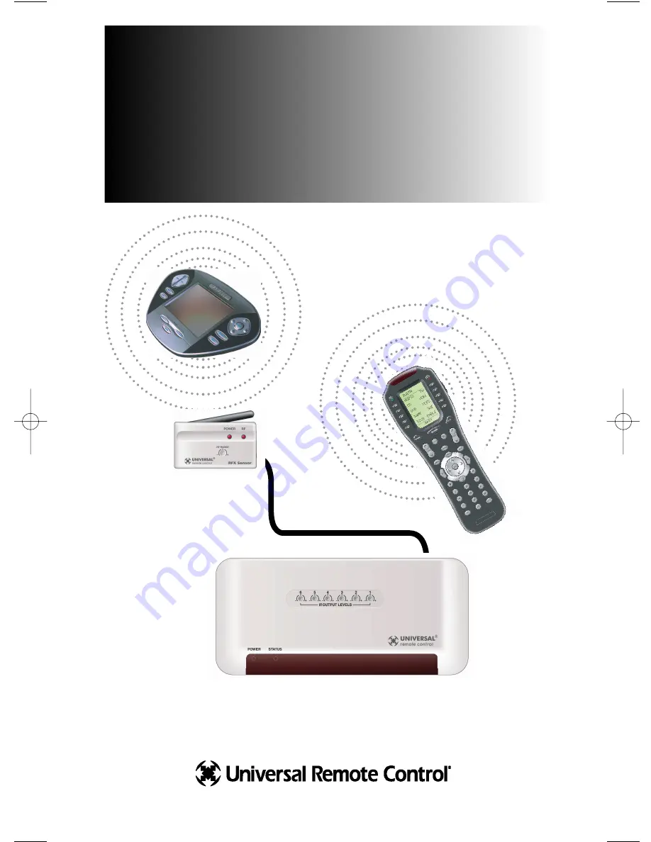
MRF-300/RFX150
INSTALLATION
MANUAL
Multi-Zone RF Base Station for the MX-3000, the Aurora ,
the Aeros , the Omega and the Osiris remote controls.
TM
MRF-300 Manual.qxd 1/14/2005 12:40 PM Page 1
Page 1: ...MRF 300 RFX150 INSTALLATION MANUAL Multi Zone RF Base Station for the MX 3000 the Aurora the Aeros the Omega and the Osiris remote controls TM TM TM TM...
Page 2: ...HALL NOT BE LIABLE FOR OPERATIONAL TECHNI CAL OR EDITORIAL ERRORS OMISSIONS MADE IN THIS MANUAL The information in this manual may be subject to change without prior notice Complete Control Aurora Aer...
Page 3: ...ion 3 Front Blaster Overload 7 Disabling the Front Blaster Step by Step 7 Controlling An Array of Identical Components or Zones 8 Identical Components Zones Step by Step 8 Programming For Multiple Equ...
Page 4: ...f your components The Flashers relay commands to components out of sight of the MRF 300 s Front Blaster The flashers plug in to the MRF 300 s rear flasher line outputs via their 10 foot cables Uniquel...
Page 5: ...ommands to the Den When you select a device located in the Family Room the MX 3000 only sends commands to it A Single MRF 300 Can Control an Array of Identical Components or Identical Zones of a Multi...
Page 6: ...hen programming the remote control b Front Blaster will be OFF and all IR line outputs are set to ALL Step 2 Mount or place the MRF 300 conveniently and run flashers to each component s front panel se...
Page 7: ...ect the RF OUT of the first to the RF IN of the next and so on down the line By daisy chaining MRF 300 s you can easily control up to 90 identical com ponents When connecting a single RFX 150 to the M...
Page 8: ...Range attenuator screw on the RFX 150 Step 6 Mount the RFX 150 and adjust for Optimum Range Have someone press buttons on the remote control from the farthest distant operating position and adjust RF...
Page 9: ...nd Cable Boxes are all extremely sensitive to IR overload or saturation Put up the on screen guide and test the navigation arrows If operation is inconsistent or sluggish LOWER the IR line output If y...
Page 10: ...RF 300 Disabling the Front Blaster Step by Step via PC Note If you are programming a URC MX addressable remote control that sets up without a PC refer to the owners manual to disable the Front Blaster...
Page 11: ...uctors connect the copper conductor to the DATA input and the silver colored conductor to the GROUND connector of the component s rear panel IR input Then adjust the line output of the MRF 300 for the...
Page 12: ...et of options for EACH of your devices By looking at the Signal column you can see that the factory default programming sets all of the devices to send both IR and RF commands If you look at the colum...
Page 13: ...d then selecting 1 6 from the seven options shown in the pull down list box Click on the cell for the first identical TV by crossing the device row with the Flashers column Select the correct Flasher...
Page 14: ...he RF Setup window by clicking on the Receivers button of the RF setup window Step 3 Add Name and Assign Receiver ID Using the controls at the bottom extended portion of the RF Control win dow add new...
Page 15: ...Second check that an opaque material like electrical tape is used to cover the flasher and the front panel sensor of each of the TV s Sometimes several layers are necessary How can I increase the rang...
Page 16: ...500 Mamaroneck Avenue Harrison NY 10528 Phone 914 835 4484 Fax 914 835 4532 www universalremote com The Complete Control Remote Control System TM...