background image


Unitronics 


M90/91™ OPLC™ 

Installation Guide 

Models 

M90/91™ 

This guide provides basic information for Unitronics’ M90/91™ OPLC™.  

General Description 

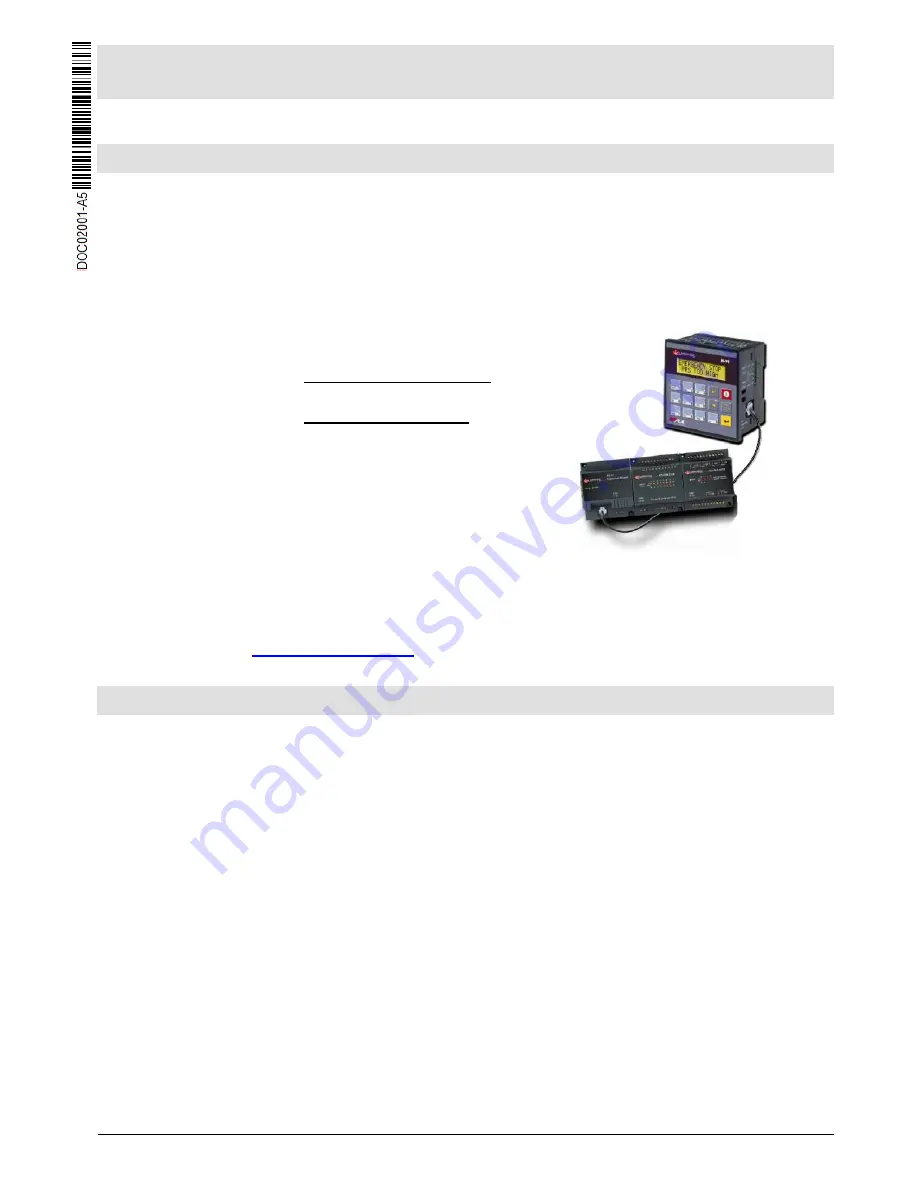
M90/91™ OPLC™ are palm-sized programmable logic controllers that comprise a built-in operating 
panel containing a multilingual text-only LCD screen and a keypad.  M90 series offer a single text line 
display. M91 offers 2 text lines.  

Communications 


  All M90/M91 controllers comprise a serial port. M90 series support 

RS232 only. An M91 serial port may be set to RS485. 

  CANbus and SMS/GSM support are model-dependent features. 

I/O Options 

M90/91 supports digital, high-speed, 
and analog I/Os via: 

  Onboard I/O Configuration 

Differs from model to model. 

  I/O Expansion Modules 

Via I/O expansion port, most 
M90 models can be 
expanded by up to 64 I/Os, 
M91 by up to 96. Check the 
specifications of your model 
for details. 


Programming 

Write both the HMI and Ladder control application using U90 Ladder freeware. 

The M90 

User Guide and the product’s technical specification sheet contain additional information. 

These documents are located 

on the Unitronics’ Setup CD. They may also be downloaded from the 

Technical Library at 

www.unitronicsplc.com


Standard Kit Contents 

M90 or M91 controller 

Rubber seal (mounted in back of panel) 

Mounting brackets (x2) 


I/O connectors (x2) 


5-pin CANbus connector and CANbus network termination resistor (CANbus models) 


Summary of Contents for M90 OPLC

Page 1: ...upports digital high speed and analog I Os via Onboard I O Configuration Differs from model to model I O Expansion Modules Via I O expansion port most M90 models can be expanded by up to 64 I Os M91 by up to 96 Check the specifications of your model for details Programming Write both the HMI and Ladder control application using U90 Ladder freeware The M90 User Guide and the product s technical spe...

Page 2: ...vice personnel should open this device or carry out repairs Failure to comply with appropriate safety guidelines can cause severe injury or property damage Do not attempt to use this device with parameters that exceed permissible levels To avoid damaging the system do not connect disconnect the device when power is on Environmental Considerations Do not install in areas with excessive or conductiv...

Page 3: ...r into the cut out ensuring that the rubber seal is in place 3 Push the 2 mounting brackets into their slots on the sides of the controller as shown in the figure to the right 4 Tighten the bracket screws against the panel Hold the bracket securely against the unit while tightening the screw 5 When properly mounted the controller is squarely situated in the panel cut out as shown in the figure to ...

Page 4: ...te that the relevant wiring diagrams are in the module s technical specification sheet and that an I O adapter is required for most modules Wiring General Do not touch live wires Unused pins should not be connected Ignoring this directive may damage the device Caution To avoid damaging the wire do not exceed a maximum torque of 0 5 N m 5 kgf cm Do not use tin solder or any substance on stripped wi...

Page 5: ...al panel Earthing the controller s power supply connect one end of a 14 AWG wire to the chassis signal connect the other end to the panel Note The wire used to earth the power supply must not exceed 10 cm in length If your conditions do not permit this do not earth the power supply Communication Ports Note that different controller models offer different serial and CANbus communication options To ...

Page 6: ...al B If a port is set to RS485 and flow signals DTR and DSR are not used the port can also be used to communicate via RS232 with the appropriate cables and wiring Before performing these actions touch a grounded object to discharge any electrostatic charge Avoid touching the PCB board directly Hold the PCB board by its connectors 1 Turn power off before opening the controller 2 Locate the 4 slots ...

Page 7: ...nto place doing so may damage the controller 7 Close the controller by snapping the plastic cover back in its place If the card is placed correctly the cover will snap on easily RS232 RS485 Jumper Settings RS232 RS485 Jumper Setting RS485 Termination To use as Jumper 1 Jumper 2 Termination Jumper 3 Jumper 4 RS232 A A ON A A RS485 B B OFF B B Default factory setting ...

Page 8: ...plicable laws at any time at its sole discretion and without notice to discontinue or change the features designs materials and other specifications of its products and to either permanently or temporarily withdraw any of the forgoing from the market All information in this document is provided as is without warranty of any kind either expressed or implied including but not limited to any implied ...

Reviews: